This thread has been locked.

If you have a related question, please click the "Ask a related question" button in the top right corner. The newly created question will be automatically linked to this question.

UCC28950: UCC28950

Part Number: UCC28950

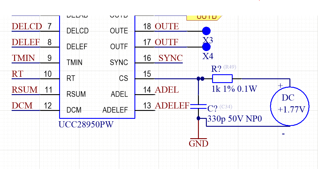
Hello. There is this signal   on the 15 pin(cs) in the UCC28950. There is a RC filter(1kOhm, 330pF) before the "CS" pin. A DC voltage source is used to drive the pin CS through the RC filter. An amplitude of the DC voltage source is + 1.77V.  A voltage loop feedback is open.Is this operation a correct? 


  • Hello Igor

    I suspect that it is correct.

    There is an internal 200-Ω pull down MOSFET at the CS pin which is turned on immediately after the PWM comparator has tripped and OUTC or OUTD goes low. The pull-down helps to set the CS signal back to zero prior to the following switching cycle and reduces the time needed to reset the PWM comparator to make it ready for the next switching cycle. You can see the effect in your plot - although the signal should get pulled down to about 300mV and I think I see it pulled down to 600mV in your plot. For some reason this internal device is not mentioned in the data sheet -.

    Your system is also running at a very narrow duty cycle - so I'd expect that the COMP pin is at a low voltage so that it commands a low duty cycle.

    Anyhow. If you decrease the 1.77V you should eventually see the duty cycle increase - the CS signal will increase, reach a peak then get pulled down.

    Please let me know if you need any more information

    Regards

    Colin