This thread has been locked.

If you have a related question, please click the "Ask a related question" button in the top right corner. The newly created question will be automatically linked to this question.

WEBENCH® Tools/TPS63806: Heating up and failing without reason.

Part Number: TPS63806

Tool/software: WEBENCH® Design Tools

Hi,

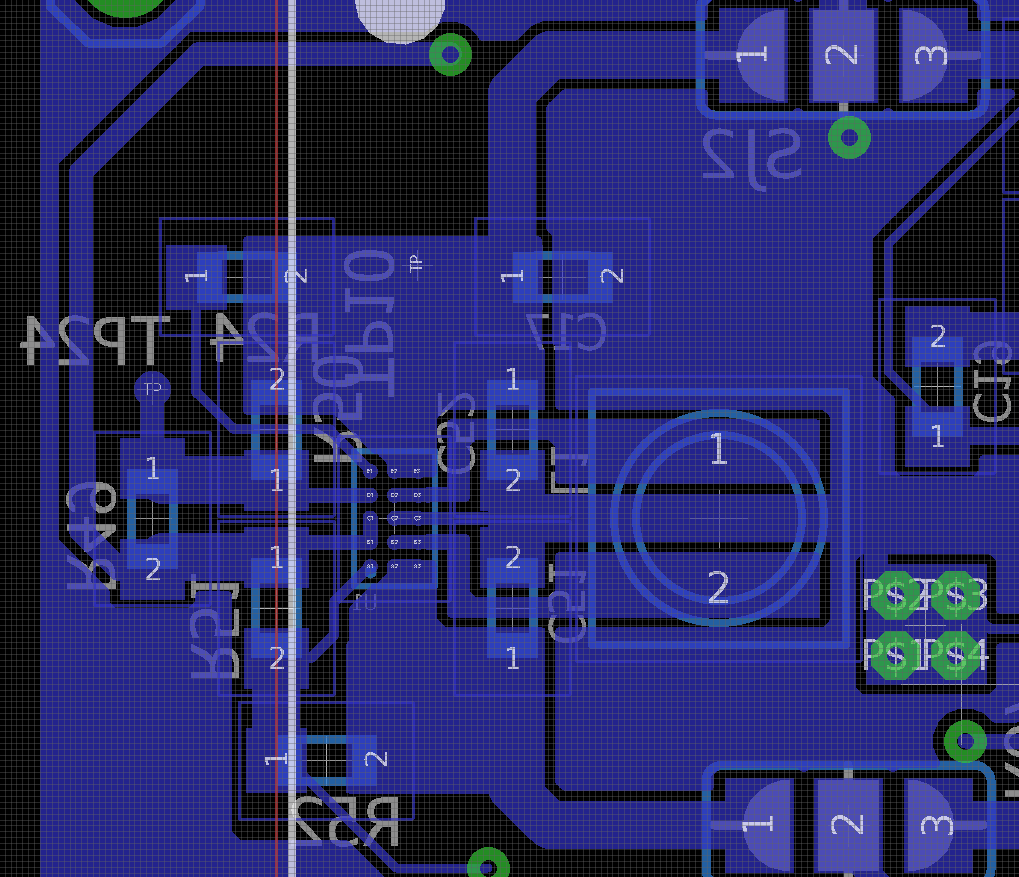
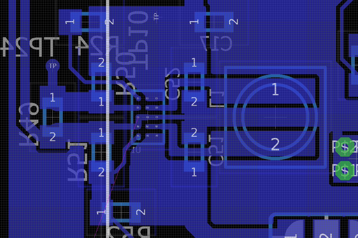
Next is the circuit I'm using to supply an IC with a 4V input and it can have some 2A peaks of consumption, designed with the WEBENCH tool:

The mode pin is connected to VDD (a 3.7 Li-Ion battery) so it should work in both PFM/PWM modes depending on the consumption.

My problem is that without reason it starts to heat up, and altough it seems to stay at 3.8V (which is less than the desired voltage, yet useful for the IC) looks like it can't supply anything.

Also after a while it goes to some mV at the output (like a short circuit) with no reason.

The best explanation I thought it was some ESD thing, due to "touching" the TPS63806 but after burning some of them and being SUPER careful of not touching it still fail.

Any idea why?

Best regards,

P

  • Hi Pablo,

    such issue normally caused by the PCB. could you review your PCB based on the suggestion in the datasheet? the input and output capacitor location are very critical.

  • Hi Jasper,

    The PCB layout is exactly the same as the one recommended on its datasheet.

    I guess I can't be wrong there.

    EDIT: Here I'm leaving the layout I'm using.

  • Hi Pablo,

    where is input capacitor and the output capacitor? which should be closed to the IC?

    the layout dosn't match the schematic. the IC is U1 instead of U22

  • Hi Jasper,

    The layout correspond to another regulator I have on the PCB, with the same IC, same layout, but different feedback resistor.

    Anyway here is the layout corresponding to the exact schematic:

    Where C51 is the 10uF input capacitor and C52 is the 100uF output capacitor.

    Any idea of what could be the problem?

  • Hi Pablo,

    the layout is not the same as datasheet. the gound trace between the input/output capacitor is much longer. could you try to rotate the capacitors to shorter the ground trace, and check again if the issue is solved. 

    did you also check if the inductor is good enough?

  • Hi Jasper,

    I separated them a bit so there is no need of using vias to connect the inductor to the IC, therefore EMI emissions are reduced. I kept that join the capacitor thick so the trace resistance is low and parasitic inductance should not be much larger.

    I can't change the capacitor places in any way to make them closer in the ground node and the inductor should be good enough, if I'm not wrong it was the one chosen by the WEBENCH tool:

    Do you know/designed any layout, small in total area covered, that works perfectly with the IC?

    Best regards,

    P

  • Hi Pablo,

    you don't need to add vias, the routing of the L1, L2 with the inductor could go under the capacitor. 

    also what i suggest is to find the root cause of the observation. we could think about the solution after finding the root cause.

  • Hi Jasper,

    I'm not sure of adding the traces under the capacitor, since it's a high current trace and the capacitors are small (0603 imperial size) so I'm concerned about the trace reliability.

    On the other hand, what's the chance of the IC causing a shortcircuit with it's own EN pin? since thats the only difference with another DCDC regulator with the same IC and that one doesn't burn, altough both of them heat up a lot. It's also recommended adding a heat dissipator or something?

    Regarding the root cause is still unknown, that's why I'm asking if there is something wrong with my layout or what in order to change/improve the DCDC regulator.

    Best regards,

    P

  • Hi Pablo,

    let's find the root cause firstly before proposing solution.  

    please experiment in the current PCB. rotate the input/output capacitor 90 degree and place them between the inductor and IC to short the ground trace. it is not hard experiment

    (please do such experiment in the new board before powering it up. otherwise the IC could be damaged before the experiment)

  • Hi Jasper,

    I tried what you said and I have two interesting results.

    First, I took a "brand new" PCB and rotated the capacitors, joining them between the IC and the inductor over their traces and here starts the interesting fact. I connected the circuitry and It seemed to work, I got a pretty stable 4V without load and it was not heating up, just in case I tried the same solution on another new board and I realized that I had connected both capacitors between them but didn't connect that point to ground, and here comes the second result.

    When connecting the capacitors joint to ground the IC heated up, probably burned, and of course no more 4V output was seen.

    What do you think is the problem?

    Best regards,

    P

  • Hi Pablo,

    i'm not quite understand about your modification and observation. could you share the image if possible.

  • Hi Jasper,

    The schematic equivalent of what I did (by mistake) that worked is the next:

    which looks like this:

    and the voltage measured at the output is:

    I'm not sure what's happening in that layout using a capacitor as feedback between input and output, I guess, somehow, is compensating the ripple backward and that together with the feedback is keeping the voltage controlled, anyway I'm pretty sure that's not the way it should work.

  • Hi Pablo,

    not, it is not the correct way. and these two capacitor are actually still in series if their connection point is connected to ground. 

    could you help to measure the VIN, L1, L2 and VOUT waveform if both capacitors are connected to ground.

  • Hi Jasper,

    The Vin waveform is a constant 4.7V - 4.8V, regarding the other waveforms your asked me for they are all 0V constant signals. I connected the joint of both capacitors to ground and the IC burns itself.

    On the other hand I don't have much more time to discuss/find out a solution, is there any layout or example circuit that are you sure it works? 

  • Hi Pablo,

    could you apply an EVM for reference? the layout can also referece the the EVM https://www.ti.com/tool/TPS63806EVM 

  • Hi Jasper,

    What do you think of the next layout?

  • Pablo,

    1. please move the input C51 and C52 closer to each other and to the IC, so the routing of the input and output loop could be minimized.

    2. I didn't realize you separate the PGND and AGND, and didn't connect them locally. if you don't have a GND panel to connect all the ground, please just connect the AGND and PGND under the IC.  (not sure if this is also the root cause of the current observation)

    3. please try to reduce the FB trace as short as possible. the FB area is too large in current layout.

  • Hi Jasper,

    1. I have C51 and C52 as close as possible, connected the way you told me to try at my actual board.

    2. PGND and AGND are conected at a STAR GND I have in the board.

    3. FB trace is as short as possible, If i try to put the resistors, from the divider, closer I would mess with the components keep out parameter.

    Can we agree that the layout I came out with should work?

  • Hello Pablo,

    Please show the PGND and AGND connection because if these get too far from each other, the device will behave not as expected.

  • Hi Brigitte,

    Here is the layout of my next power supply prototype:

    the four vias on the down-right part of the picture is where all the grounds get toghether (Star ground)

  • Hello Pablo,

    Please connect AGND and PGND directly at the IC. This is too far away for best performance.

  • Hi Brigitte,

    Something like this should work, right?

    On the other hand,

    what's the purpose of different ground path if I'm connecting them together on many points?

    I only have feedback and enable resistor divider connected to AGND, so performance shouldn't be affected that much as long as they have a good ground plane and both ground keep the same voltage, right?

    Does Texas instrument have any document or something that explains how to design a good grounding?

    Best regards,

    P

  • Hi Fabio,

    the routing of the input capacitor and output capacitor could be further reduced if move C51 and C52 closer to the center of the IC and closer to the IC. 

    about the layout AN, refer to  https://www.ti.com/lit/an/slva773/slva773.pdf and https://www.ti.com/lit/an/slyt614/slyt614.pdf 

  • Hi Jasper,

    I can't place C51 and C52 closer without messing with the keepout layer of the CAD, also the layout looks pretty much like the evaluation board layout but without vias to reduce EMI.

    Can you show me what do you mean by placing them closer, since I don't understand how.

    Best regards,

    P

  • Hi Pablo,

    in the EVM, C1 and C6 is quite closed. actually, the 16~20 mil distance of the Pads of the capacitor is good enough.