This thread has been locked.

If you have a related question, please click the "Ask a related question" button in the top right corner. The newly created question will be automatically linked to this question.

BQ25882: About charging operation.

Guru 11245 points
Part Number: BQ25882

Hi team.

My customer found strange behavior during the test.

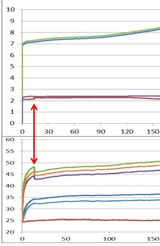
About 13 minutes after charging 200mA, the IC surface temperature decreased by 2 ℃.

At that time, charging current has increased from 213mA to 228mA.

However, other charge currents(400mA) will not cause this phenomenon..

The measurement data is shown below.

Upper graph: Red line is charging current.

Under graph: Green line is IC surface temperature.

Please give us any advice on this phenomenon?

I'd like to know why this phenomenon occurs.

Sincerely.

Kengo.

  • Hi Kengo,

    As the battery voltage increases, the charger's output power increases and so the IC gets hotter.  If the battery voltage rising above MINSYS, the current regulation changes from the MINSYS loop across the BATFET to the PWM loop, which results in a regulation point shift.    If the converter is moving from PFM to PWM, then the current sensing amplifier sees different noise levels which cause the regulation to change slightly.  You can test the PFM theory by disabling PFM mode and retesting.  Note that both values are still within the +/-25% regulation accuracy. 

    Regards,

    Jeff