This thread has been locked.

If you have a related question, please click the "Ask a related question" button in the top right corner. The newly created question will be automatically linked to this question.

UCC28070A: UCC28070A Single Phase PFC, DC input works, AC input does not work, no even one switching event

Part Number: UCC28070A

Hello, 

I am using UCC28070A designing an single phase pfc (~400Vdc output), 

The schematic related to this controller is as follows:

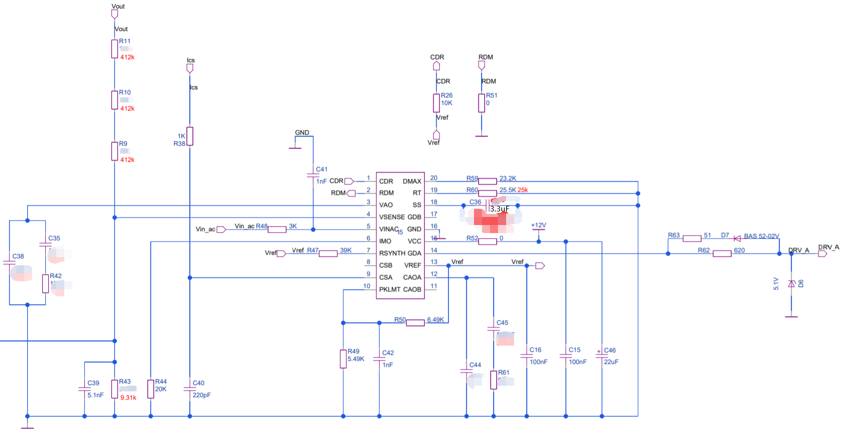
I tested it, and the result is, while +dc or -dc input, in the range from 120Vdc~380Vdc, it works well both light load and full load.

But when I switched to AC input condition, it doesn't work.

The waveform at ss pin I think is abnormal which is as follows:

Test condition: 150Vac@50Hz     0.2A Load;

Blue: pfc output voltage;                 Green: ss pin voltage;               Red: you can think of it as the 50Hz input AC voltage although actually it's not;              Yellow: input ac current;

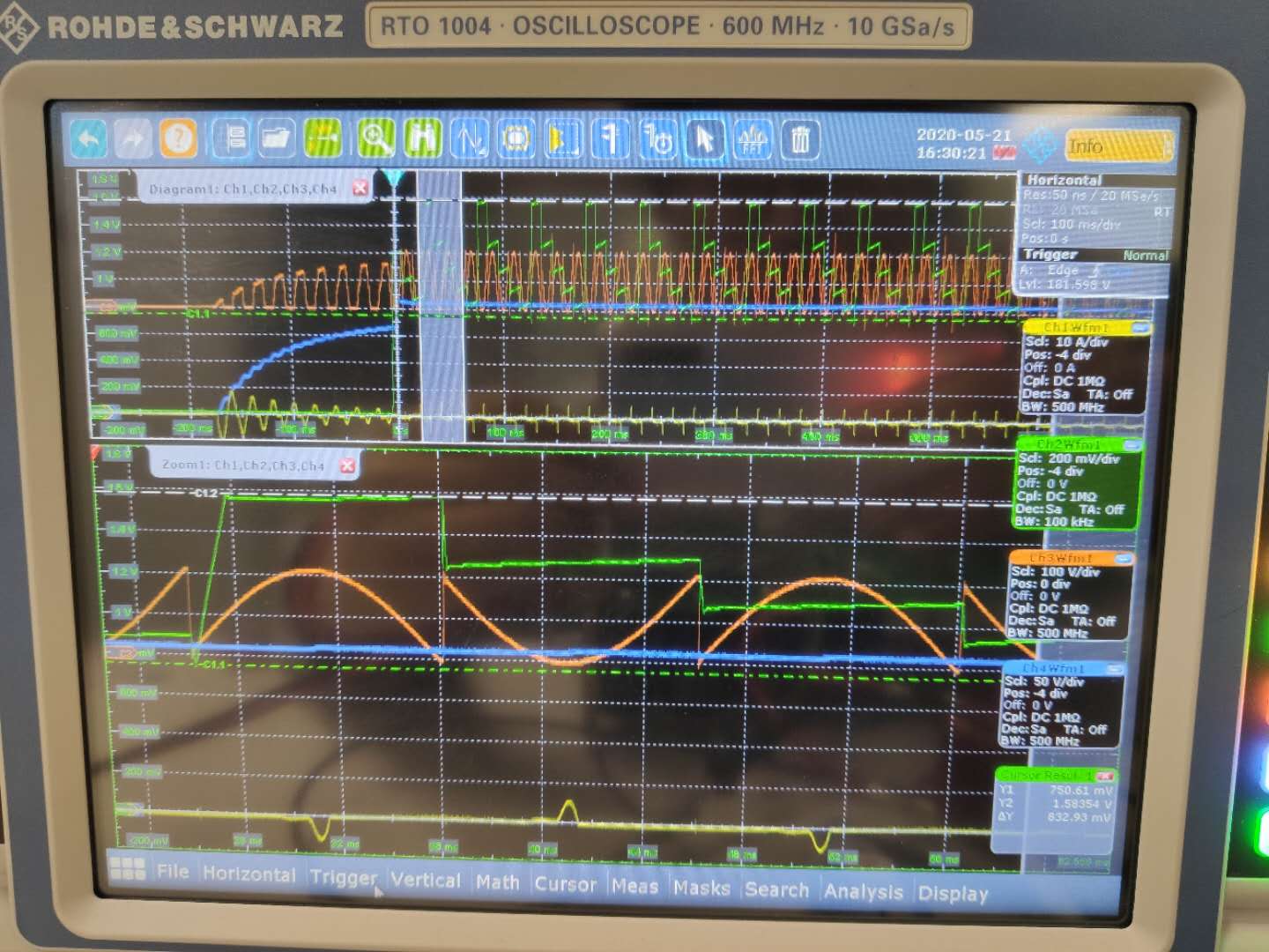
You can see every time Vss(voltage at ss pin) reaches Vsense(I calculated and found that it equals to VSENSE when Vss starting to decrease), it starts to decrease a little at every ac zero-cross point until it reaches 0.75V, then re-start.......... No even one switching event had happened.......

While in dc input condition, everything is right.

Thank you so much.

B/R

Jankel.

  • Hello Jankel,

    You need to attach the complete schematic with component values used.
    Also you should use the Excel calculator tool and attach the results so that your design requirements are known.

    The embedded image you posted does not have enough information to answer your question.

    Regards

    John

  • Hello John,

    Other information is not useful to this question.

    Control Loop is definitely stable based on my small-signal modeling and compensation calculation which is already verified by my simulation, so I didn't show the initial control loop component values which caused unstable before to make sure no confusion would exist. (In addtion, the excel and mathcad calculator TI offered are not suitable for my application because they are for the two phase interleaved topology rather than one phase. That's why I didn't use this unsuitable excel, so I didn't attach it.)

    Please keep in mind that while in dc input condition either positive dc input or negative dc input, everything is right.

    The only thing I want to know is what may cause this issue? Do you have any experience of this kind of Vss waveform?

    Best Regards

    Jankel Cao