This thread has been locked.

If you have a related question, please click the "Ask a related question" button in the top right corner. The newly created question will be automatically linked to this question.

LMR14050-Q1: Lose out put with loads

Part Number: LMR14050-Q1

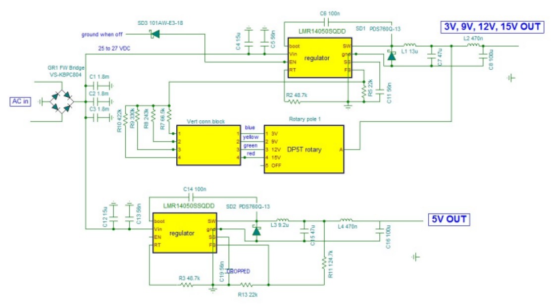
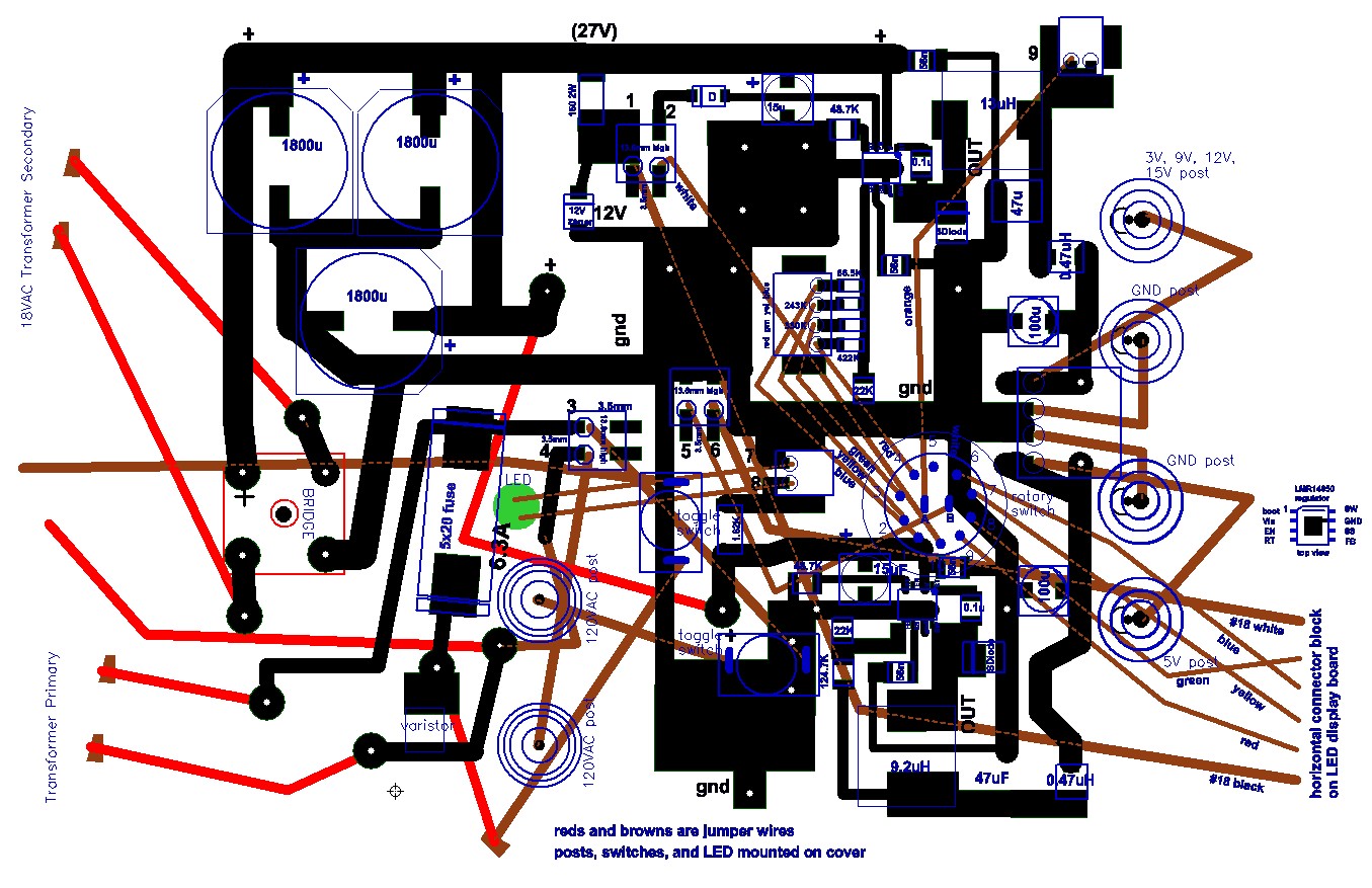
I am building a dual hobbyist power supply with two LMR14050s, one for a fixed 5 volt, the other for a switchable 3V, 9V, 12V, and 15V (schematic attached.)   I have run into a few problems, mostly my own doing that were rectified, but now have one that has me baffled.  For the first time I applied loads to the output:   a 10 ohm resistor on the 5V and 50 ohms on the selected 15 volt output.  (My intention was to measure the heat sink temperature rises.)  With the load attached the output voltages dropped:  to a few mV from 4.99V for the 5V output, and to about 45mV from 15.12V for the 15 volt output .  When the loads were removed the output voltages returned to spec.  I went through this process about five times to prove I wasn't dreaming.   Any ideas why????

  • Hi Rod,

    This might be just a measuring error. Can you please send a photo of your probes, showing how and where exactly you are measuring output voltage.

    If you are measuring the output voltage away from the output cap, then it might be just IR drop from traces.

    A photo will help here.

    Best Regards,

    Ankit Gupta

    Application Engineer

  • Hi,

    Firstly please check the input voltages when you connect the loads to check if the input current is limited. Thanks. 

  • The input voltage does not change, stays around 25V

  • Thanks.  I thought about that as my DMM gets fickle once in a while.  But I took measurements 5 different times, and the current flowing through the load resistor matches the 45mV measured output voltage.  It is unlikely that the 6"-8" of traces and connection wires would drop 15 volts.

  • The voltage on the FB pin is about 1.8mV with the low mV output voltage with the 50 ohm load connected.  It is 0.77V with no load.  Don't know if the low FB voltage is a cause or a result of the problem, but everything I know says it is a result as the FB voltage derives directly from the OUT voltage through the resistor divider network.  So, this might not be helpful information but though I'd pass it on for completeness.  Would the over-voltage lock out or the over current oscillator frequency adjustment, both effected by the FB pin voltage, have anything to do with this?

    Another thing:   The output voltage sometimes, at least, varies with a steady decrease.  When first powered on this morning I got about 3V from the 15V switch setting.  About 15 seconds later it had dropped to about 1V.  Another 15-30 seconds to about 400mV.  Within a minute or two down to a steady 45mV.  However I don't notice this every time -- maybe it is there but I simply don't see it, or maybe it is not always there.  ?????

  • The drop on the output voltage is load dependent.  With any load greater than 250 ohms to 500 ohms (I can't pinpoint it exactly) the voltage stays precisely on spec.  With lesser loads the voltage drops off I suspect linearly -- at around 100 or so ohms the 12v selected output puts out about a steady 4 volts.  This means that voltage drop begins at a load current of about 48mA or more [12/250).  It doesn't seem that Over Voltage Protection, current limit or short protection current restriction operate in a manner that would cause my problem, but I do not know that for certain.  Thoughts?

  • Hi,

    Please attach your layout and components part numbers, let's check the trace width and components ratings first. Thanks.

  • OK.  This might be a duplicate post.

  • Hi,

    What are the red and brown traces? Are they PCB traces? If so, they are to narrow, please use much wider traces especially power in/out ones.

  • The red and brown lines are jumper wires, brown above board and red below board.  All traces and pads are black.  Blues are component outlines and notes.

  • Hi,

    Could you please lower the output current and test it again to see how heavy the current that will cause a output drop? Also it looks too many jumpers will cause noise in circuit, could you please remove all unrelated jumper and test it again? Thanks.

  • I made a little more accurate measurements (though they are still rough because of the gross margins in the potentiometer) of the 3V, 9V, 12V and 15V outputs.  All maintained their voltage out until the load dropped to 50 ohms to 250 ohms or so at which point the output voltages dropped precipitiously.  I suspect the actual cutoff load is different for the different voltages but I can't measure them that closely. This says 100mA to 300mA is the highest current the regulator will put out.  

    I can't remove the jumpers and keep the circuit working.  But in reading more about layouts of switching regulators in TI's application note, one thing bothers me in the jumper wire category:  To switch between voltages there is a jumper from the output to the rotary switch mounted on the box cover that runs right over the output inductor,  Then there are four jumpers from the rotary switch to the four FB top resistors which are placed very near the FB pin.  Each of these jumpers are 22 gauge and about six inches in length.  Your application note says this is not a good layout.. There is very little that can be changed other than shortening the jumpers to maybe three inches.  I can also wrap shielding around the jumpers.  What do you think? 

  • Hi,

    OK, it looks the long wire of FB couples noise when the load is heavy. I don't recommend to use a shield because it not easy to find a good shielding ground, just shorten the trace please.