


Dear TI support forum,
We are currently designing a power management system using the TPS2121 IC. The goal is to design a board that can control whether or not power is being drawn from ground systems (an external power source) or an on board battery pack. When ground systems power is disconnected the board should be able to seamlessly switch to the battery pack.
Our first test involved setting up the IC as shown in page 25 of the datasheet, Automatic Switchover with Priority (XCOMP).
Here is a summary of our test results:
-
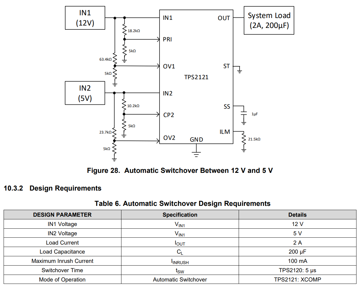
Using the input voltage of 12V and a simulated load of 2A, we achieved a switching time of 50 microseconds. Resistor values were not exact, but achieved a switching voltage very close to the desired value. We recorded switching at 7.75 V, while the expected value was 7.6V
-
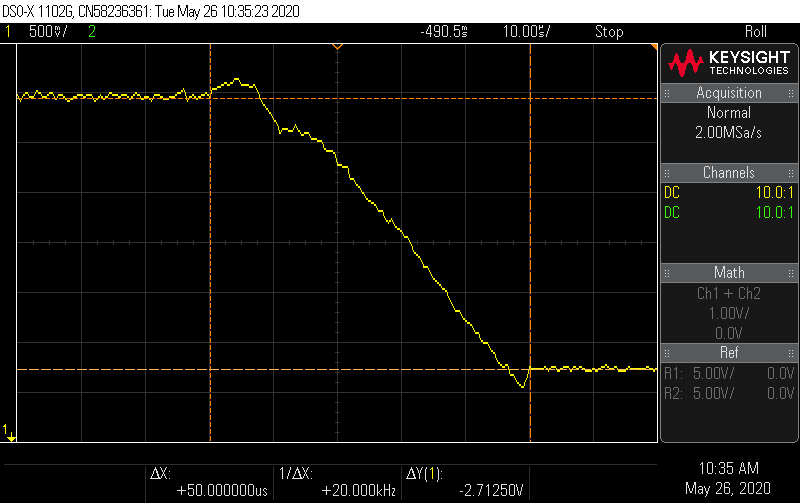
When one input is set to 12 V, and is then one is then suddenly disconnected, we observe a voltage drop to zero and then a ramp up, with a switching time of 207ms. This is done without any capacitor to smooth the output voltage. The ramp indicates that the current limiter is working.
-
Overvoltage protection works well: When the input is increased past the designated value, the output switches to 5.0V
-
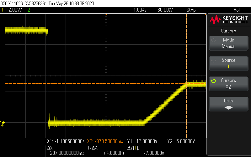
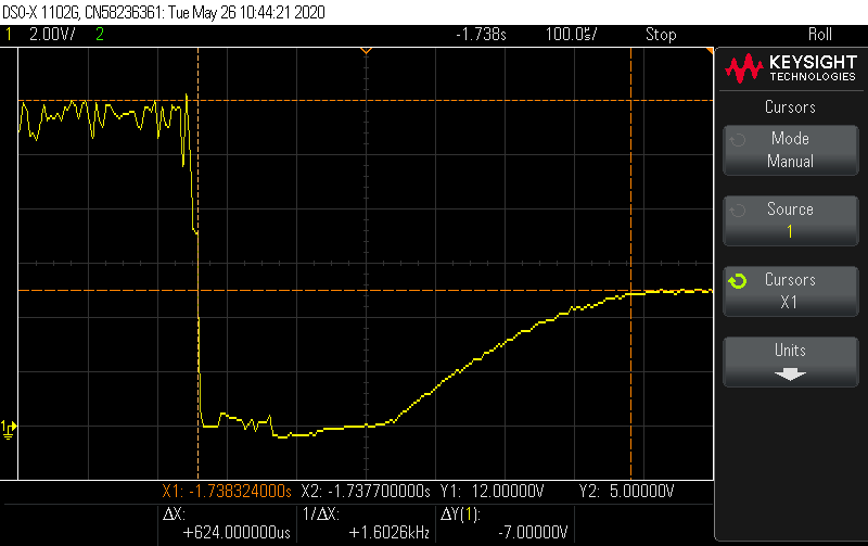
Had trouble reducing switching time: modified the SS (pin 11) by reducing capacitance to 100pF. To further minimize the switching time, we increase the slew rate by reducing the resistance of ILM output (Pin10) 17.6 kOhm. This produces a switching time of 624 microseconds.


Our current problem is that the switching time is far too slow and the output has a significant dip while switching. We have tried buffering the output with a 220uF capacitor to ground but it only seems to slow the switching time.
