This thread has been locked.

If you have a related question, please click the "Ask a related question" button in the top right corner. The newly created question will be automatically linked to this question.

BQ24610: About small fast-charging current and small precharge current setting

Part Number: BQ24610

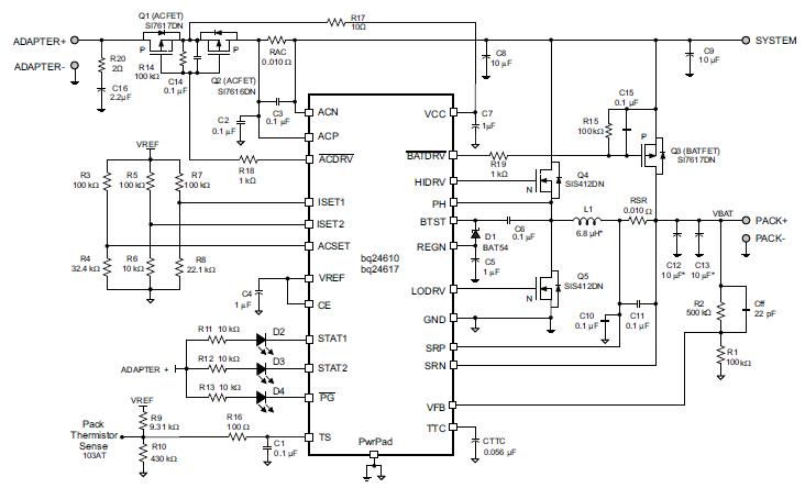
Dear experts, please refer to below figure. I set the fast-charging current to 50mA and set precharge current to 10mA. R7 is 100K ohm, R8 is 43.2K ohm, R5 is 100K ohm, R6 is 43.2K ohm and RSR is 1 ohm. L1 is 6.8uH. The ADAPTER+ is 16.8V and PACK+ is 11V(3 *Li iron battery). The real fast-charging current is about 12mA. The fast-charging current will depent on PACK+ voltage. When I increase the PACK+ voltage, the  fast-charging current will reduce.  When I reduce the PACK+ voltage, the fast-charging current will increase. Could you give me some suggestion how to achieve the 50mA fast-charging current and 10mA precharge current. Thanks.

  • HI Jason,

    50mA fast charge current, and 10mA precharge current are extremely low current values for this part. Setting 1ohm sense resistor is extremely high, and has not been validated with such a configuration, as this part was intended to fast charge, as opposed to trickle charge at such low current. 

    I would not recommend this part for 10mA precharge/termination current.

    Can you capture PH, HIDRV, LODRV on scope capture? This way we can identify if part is in DCM or CCM, to further debug, although it is highly unlikely that this part can achieve 50mA fast charge, and 10mA precharge/termination with accuracy.


  • Dear Kedar, I set the fast charge current to 80mA, R7 is 100K ohm, R8 is 93.1Kohm and RSR is 1 ohm. L1 is 6.8uH.The ADAPTER+ is 16.8V and PACK+ is 11V(3 *Li iron battery). The real fast-charging current is about 37mA. Please refer to below figure. Thanks.

  • Dear Kedar,

    I have updated the figure of PH, HIDRV and LODRV. I change the fast-charging current to 80mA . R7 is 100K ohm, R8 is 93.1K ohm and RSR is 1 ohm. L1 is 6.8uH. The ADAPTER+ is 16.8V and PACK+ is 11V(3 *Li iron battery). The real fast-charging current is still less than 80mA(about half of 80mA). Could you give some suggestion? Thanks.

  • Hi Jason,

    As the charge current sensing is so low, the converter is operating in DCM, to prevent negative inductor current, and turns off the LSFET. This is why the PH(switch node) waveform looks like this, as for the rest of the falling inductor cycle, both FETs are off. In DCM there is less current accuracy, so achieving high charge current accuracy at such low currents with this part is not possible. This part was not designed to operate at such low charge currents (trickle charge) and is meant to accurately fast charge the battery.

    One option is to try a higher inductance value for the inductor, which results in lower inductor current ripple, which might help the internal current sense accuracy by reducing valley of the inductor current.

  • Dear Kedar, I hope the fast charging current is about 50mA and pre-charge current is about 10mA~20mA. If this component is not suitable, could you suggest another part for my application? Thanks. 

  • Hi Jason,

        The fast charge and precharge current settings are extremely low, for which our linear charger portfolio is ideal. However the high input voltage and output voltage requirements for your system, mean that linear chargers would not be possible to use. This is not a common requirement we have seen, for high battery voltage and such low current, and we don't have charger IC that can fit your system.

  • Dear Kedar, Thanks for your reply. I have another question about bq24610. If I set the ADAPTER+ voltage to 24V and PACK+ fully charge voltage to 12V (3 *Li iron battery, 3*4V=12V), does it will has any side effect(such as low energy convert efficiency due to high voltage gap between ADAPTER+ and PACK+) ? Thanks.

  • Hi Jason,

       There is a tradeoff regarding efficiency, assuming output voltage remains the same in both cases (which is your case). Higher input voltages, result in higher switching losses. However, lower input voltage results in a higher duty cycle, which results in increased conduction losses (there is also more efficiency loss across the input reverse blocking FETs, as in high duty cycle the input current will be larger). Higher input voltage also results in increased gate driver loss

    As BQ24610 is a charge controller, efficiency is dependent on selection of external components and layout. For example, if gate driver losses are a huge concern, then lower Qg switching MOSFETs can be used. Or if conduction losses are a huge concern, then lower inductor DCR, lower switching FETs RDSon can be used.

    Section 10.2.1.2.4 Power MOSFETs Selection of the datasheet shows the efficiency calculations and considerations.

  • Dear Kedar, Thanks for your help.