This thread has been locked.

If you have a related question, please click the "Ask a related question" button in the top right corner. The newly created question will be automatically linked to this question.

TPS62423-Q1: High input current in idling desing

Part Number: TPS62423-Q1
Other Parts Discussed in Thread: TIDA-020002

Hello, I have designed camera module (for prototyping at the moment) with TPS62423-Q1. Due to size cosntrains I went with VLS252010CX-2R2M-1 inductors and 0402 output caps. Without input cap circuit seems to be working, it sinks around 7mA when idling. However, when i do solder input capacitor (and I tried 100nF, 1µF, 4.7µF and 47µF - last one was chosen as a system cap for the board) current rises to 300mA and converter starts to heat up. What is going wrong?

  • Hi,

    Please provide more information to support here.  Layout and caps placement have a major impact on device performance. Could you provide the layout and schematics of the application? The capacitor used as input are ceramic caps? It information is confidential I would suggest it through the mail.

    Best regards,

    Tanvee

  • Hello, Schematic was "stolen" from TIDA-020002 with one exception: got MODE pin tied to ground. Here is converter section (Bottom layer - blue) with continous ground plane on internal layer.

  • Hi,

    The layout looks okay. Could you confirm the capacitor used are ceramic?  

    And could you just measure the input voltage and current before and after input capacitors?

    Best regards,

    Tanvee

  • Hello,
    as input capacitor I've originally used GRM188R60J476ME15J (47µF/6.3V X5R, at 5V it derates to around 20% nominal capacity) parallel with C0402C104K8RACTU (0.1µ, 10V, X7R). I've also tried two 0805YC475KAT2A (4.7µ, 16V, X7R).
    As of the output, my first try was GRM155R60G106ME44J (10µ/4V), but I also tried two of 4.7µ/10V and even 22µ/6.3V.

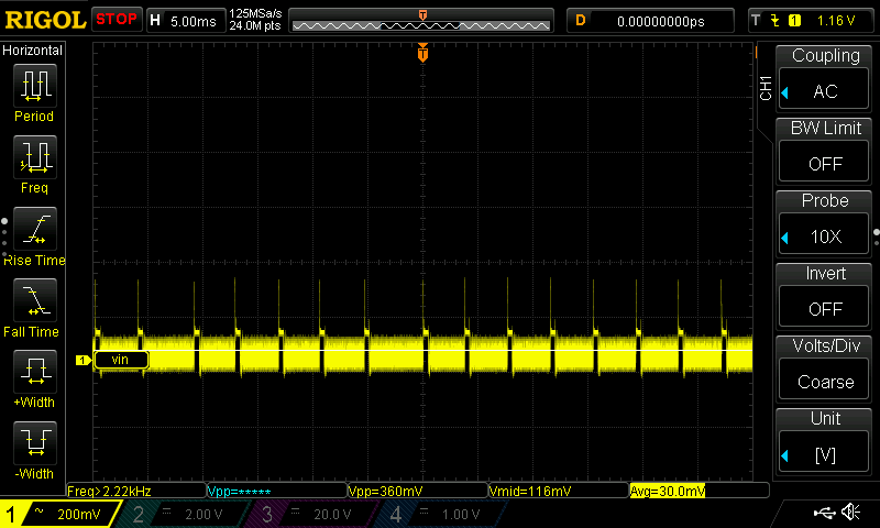
    I am attaching voltage ripple at input cap (2x4.7µ). Current waveforms are not measurable at the moment - I have no current probe (and even worse, not a single resistor in typical shunt range - home office reality). However current starts to rise at power up. 

  • Hi,

    Sorry for the delay.

    I can understand the situation but from Input wave from is also not looking constant. Suppl is from the other controller? I asked for the current measure because the ceramic capacitor has high ESR and It will affect the supply and that's the reason the device is showing strange behavior.

    Best regards,

    Tanvee

  • Hello, supply is from Keysight E36312A (current limit is off), however in next applications it was meant to be powered with another DC-DC converter (as it will be powered over coax). What is recommended ESR value for this converter? As for AVX 0805YC475KAT2A has ESR=2mΩ @ 1MHz. Due to size constrains I will check another converter, all other TPSxx are working fine. 

  • Hi,

    I am talking about the capacitor ESR here. All other buck is using the same capacitor bank on the input side. Because Buck is working good without cap bank and placing it is consuming more current right? And the reason I asked wave from before and after cap bank.

    Best regards,

    Tanvee