This thread has been locked.

If you have a related question, please click the "Ask a related question" button in the top right corner. The newly created question will be automatically linked to this question.

LM5155: 40V to 300V booster - IC destroyed

Part Number: LM5155

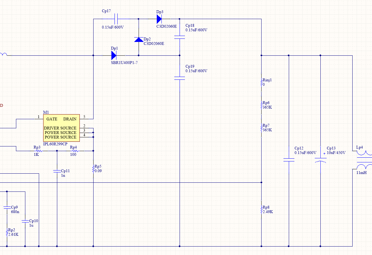
I'm having an issue with the following boost design. This is basically straight out of the Webench software with minor adjustments. Input voltage is 35-45V, Output voltage is 300V, output current is 20-30mA.

On power-up the LM5155 is destroyed with a spark. Dp1 fails short-circtui as well. I'm not sure what happens first. Dp1 is 400V rated, so it should be within it's operating margins. I've tested this circuit with Rp6 shorted and it worked fine. Output was around 145V.

Any ideas as to why this circuit fails at 300V output?

  • Hi Ilya,

    Thanks for reaching out with your question and for using the LM5155 in your design.

    I am looking into the issue now. Can you tell me what application this is for?

    Thanks,

    Garrett

  • Hi Garrett,

    Thanks for chiming in. This is intended for all sorts of low level tube audio gear - preamps, compressors EQs etc. So I won't need a lot of power, but I need it to be clean (but that's another topic).

    I'm currently waiting for replacement parts, so I designed a "plan B" circuit. Since this booster worked fine at 150V, I think it should be possible to put a simple voltage doubler and wrap a feedback around it like on the picture. I'm not sure if Cp17-Cp19 are large enough for supplying 30mA, but given that Cp13 is 10uF, I hope it should work. Please tell me what you think.

    And it's really curious to find out what happens with a plain 300V design.

    As a sidenote, I did a Webench design of the 150V booster to see if the compensation is different, and I can't find any data on the phase margin in the Webench design summary. If the system calculates component values, it should estimate loop responce. But I don't see it anywhere.

  • Hi Ilya,

    The first think I suggest to test on the 300V board, is removing the EMI filters and moving powering the circuit directly after LP2. There might be some instability between the input impedance and the EMI filter. This could cause the input voltage to ring and damage the LM5155 by providing the BIAS pin with > 50V which could damage the device.

    I also suggest changing up the loop compensation for the 300V board.  CP10 looks to large at 1uF

    RP2 = 50kOhm

    CP9 = 47nF

    CP2 = 120pF

    Please let me know if you have any questions.

    Thanks,

    Garrett

  • Garrett Roecker said:

    I also suggest changing up the loop compensation for the 300V board.  CP10 looks to large at 1uF

    RP2 = 50kOhm

    CP9 = 47nF

    CP2 = 120pF

    Thanks Garrett. Will test your suggestions.

    CP2=120pF doesn't make much sence. Do you mean CP10=120pF?

  • Ilya,

    Yes I intended to type C10 = 120pF.

    Thanks,

    Garrett

  • Hello Garrett,

    One strange thing is: I had to increase the SS cap a lot in order for the circuit to start up. Otherwise it couldn't start and reach the target output voltage. My final working unit uses around 60uF of capacitance in order for the chip to start properly while loaded.

    Looks like the diode gives up first. I was not able to make the circuit work when applied power after the EMI filter directly. So I chose to use voltage doubler and make a 150V boost stage.

    I've done some experiments with the loop compensation using both your suggested values (I know they are for 300V, but still) and values from the Excel LM5155 Boost Controller Quick Start Calculator (SNVC224, 150V, 0.04A out). With your values the circuit behaves much better. The calculator suggested 146K + 4.6nF and 51p (Chf). These values made the controller to skip some pulses.

    My only concern now is the efficiency. Right now it's around 62% (150V into doubler, loaded with 0.02A). Calculations show the efficiency should be in the order of 75-85%. What may be causing this low efficiency? I thought that it's the inductor (1 Ohm resistance), and it gets quite warm (together with a MOSFET). But calculations don't support this low efficiency even considering the high resistance of the inductor. Can the low Rsence (90mOhm) be the culprit?

    EDIT: Inductor temp is 62C, MOSFET temp is 85C, LM5155 temp is 56C, Dp2 temp is 48C. Duty cycle is 28%.

  • Hi Ilya,

    For the first circuit (not voltage doubler), is the diode seeing some type voltage stress? It is not clear why this would be damaged first. Also 60uF seems to be too large for the SS capacitor. 

    For the second circuit, I think the RDSON of the MOSFET and the RDCR of the inductor should be reduced. It sounds like there is a lot of power dissipation coming from these devices.

    Thanks,

    Garrett 

  • Hi Garrett,

    I changed the diode to the other (the same used in the doubler) and the efficiency jumped to 72-75% (20mA load, 300V) - I think it has something to do with the reverse recovery time which is rather long (85nS in the old diode vs "zero recovery" in the new on). I tried to lower the switching frequency and it increased efficiency even more, I was able to get 80% at 30mA load.

    However, my main problem now is the circuit won't start up reliably. With no load it starts fine (although with a huge capacitance on SS pin). But if I start it into 20mA load, it won't start. The voltage ramps up to aproximately 200V (after the doubler) and the switching stops, voltage drops to zero and everything starts from the beginning. I tried different compensation values and got no result. I tried to change the slope resistor and it didn't help too. I feel like I'm almost there. Where should I look in order to solve this startup issue?

    Thanks!

  • Hi Ilya,

    Are you using the LM5155 or the LM51551? The LM5155 has hiccup mode enabled. Based on your description is sounds like the device if running into hiccup mode. I would suggest using the LM5155 which just has normal cycle-by-cycle peak current limiting.

    Thanks,

    Garrett

  • Hello Garrett,

    Indeed, you are right. I checked the labeling and it differs from the other chips (I got some chips from one source, and some from another). Looks like one of the suppliers shipped the LM51551 instead and that's why I had all these problems with the chip not starting up properly.

    I'm now able to get the 75-80% efficiency and a reliable start-up. Output ripple is less than 10mV, and output noise is less than 3mV RMS (10Hz - 100 kHz) which means I don't need additional linear post-regulation stage. I'll see if a smaller inductor will improve the efficiency. But overall, this result is acceptable. Thanks for your help. And that Excel calculator gives much more useful results than Webench, at least for my case.

  • Hi Ilya,

    Thanks for letting me know that you were able to get the issue fixed and the the LM5155 is meeting your requirements. 

    I am going to close this thread for right now. If you have any other questions please let me know.

    Thanks,

    Garrett