This thread has been locked.

If you have a related question, please click the "Ask a related question" button in the top right corner. The newly created question will be automatically linked to this question.

LMR33630: LMR33630 invert circuir issue

Part Number: LMR33630

Hi team,

our customer use below circuir for invtert DC/DC:

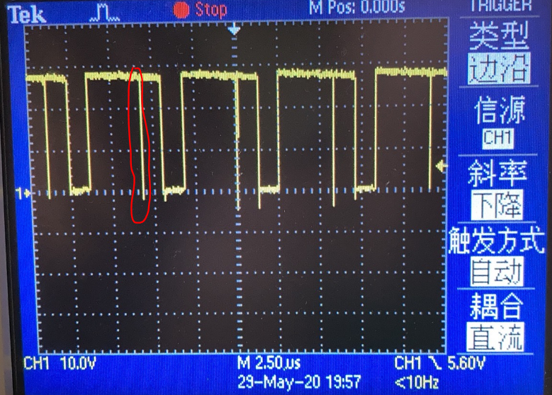
When input is 7V, output is 12V, load is 51ohm, every thing work good, but when change the Rfbt=180kohm, then output change to -21V, and use the same 51ohm load, DC output is right, but SW wave shows issue as below:

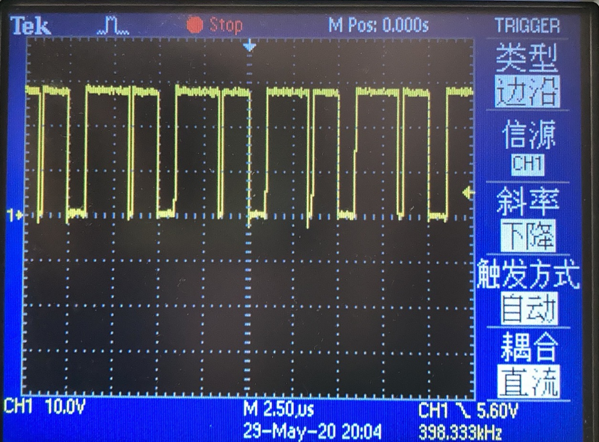
if change the load to 100ohm, issue seems become more terrible:

could you help to share some comments on why this happened and how to fix the issue?

Thanks very much,

Regards, Sunny

  • Hi

    Could you please help probe voltage between Cboot? You can change another Cboot with higher voltage rating or a larger Cboot then test the converter again.

  • Hi Iven,

    Thanks for your comments, when I changed the boost capacitor to 334/50V(input 7V, output -21V, load 100ohm), issue keep same, below is the scope wave:

    do you have any other comments?

    Thanks very much.

    Regards, Sunny

  • Hi Iven,

    Thanks for your comments, when I changed the boost capacitor to 334/50V(input 7V, output -21V, load 100ohm), issue keep same, below is the scope wave:

    do you have any other comments?

    Thanks very much.

    Regards, Sunny

  • Hi,

    It looks the inductor is not large enough referring to Equation 5 in its datasheet, please change to a 15uH at least or 22uH inductor. Also could you please upload the PCB layout? If the feedback resistors are not close to device, there will be some noise coupling making loop unstable. Thanks.

  • Hi Iven,

    Many thanks for your comments, when changed the inductor to 47uH(as no 22uH on hand), SW issue disappeared. Thanks again.

    But we meet another issue: when input is 7V, output is -21V, if power on with no load, and then add 100ohm load, everything works good, but if add the load then power on, it can`t power on, output can`t set up.

    then i add 470uF input capacitor paral with Cin, nothing changed, but if I removed output 68uF capacitor and only leave 22uF output capacitor, then it can power on with 100ohm load.

    but customer do need larger output capacitor, do you have any comments why it can`t set up with 68+22uF load, and how can improve it if we must to add more than 100uF output capacitor?

    Thanks.

    Regards, Sunny

  • HI lven,

    One more qustion, why we need D1(a samll current diode) for the invert application?

    Thanks.

    Regards, Sunny

  • Hi,

    1. With a large Cout, the start-up current rush will large and trigger current limit. You can put an inductor to limit the rush current and put feedback connection before the inductor to avoid any loop unstability.

    2. The diode is used to clamp any possible positive voltage on the negative output terminal.

  • Hi Iven,

    Thanks a lot.

    Regards, Sunny