This thread has been locked.

If you have a related question, please click the "Ask a related question" button in the top right corner. The newly created question will be automatically linked to this question.

TPS22969: output turns ON to partial value witout a enable signal

Part Number: TPS22969

 we have used TPS22969 load switch for one of our design , this design requires a specific power on sequence, while probing the output of the load switch we found that the there Is 1.8V present at the output pin even when the enable voltage is 0. this creates a unwanted step in the power sequence in the CPU.

As long as the enable is in 0V the output remains at 1.8V , when the enable is provided the switch conducts to 3.3V volts.

Please let us know how to solve the issue.

  • Hi Vineeth,

    Welcome to E2E!

    The ON-pin of the load switch is designed to work as a logic controller to the switch. If the ON-pin has 0V or GND then the device will remain off and no voltage or current will go through the device. Once the voltage on the ON-pine exceeds the VIH threshold of 1.2V then the switch will turn on and begin conducting from VIN to VOUT.

    I have a couple questions to troubleshoot this problem you're seeing:

    You mention that there is some power sequencing going on in your design. what are the other power rails in this system?

    Have you been able to replicate this behavior by isolating the TPS22969? (i.e. are there test points by the TPS22969 that you could use to apply the 5V to VBIAS, 3.3V to VIN, and toggle the enable pin to observe the on pin without turning on any other power rails?)

    When the device is disabled and you see the 1.8V on the output of the TPS22969, are you able to measure the current being supplied by the 3.3V power supply?

    Best regards,

    Andy Robles

  • Q1. Have you been able to replicate this behavior by isolating the TPS22969? (i.e. are there test points by the TPS22969 that you could use to apply the 5V to VBIAS, 3.3V to VIN, and toggle the enable pin to observe the on pin without turning on any other power rails?)

    yes, this is the same case even if I switch off all other rails.

    Q2. When the device is disabled and you see the 1.8V on the output of the TPS22969, are you able to measure the current being supplied by the 3.3V power supply?

    Are you asking to load the output of the SWITCH, and see if the voltage drops from 1.8 V to a lowerd value?

    Also I cut the trace to the BIAS pin and supplied with 3.3V to BIAS, the output drops to 0.8V with out enable applied.

    Please let me know how to solve this issue? is this the problem with the Switch?

  • Hi Vineeth,

    Has this test been done with multiple devices or with only one TPS22969?

    With no enable signal the resistor R352 should be grounding the ON-pin disabling the switch completely. The output you're seeing on the OUT pin of the TPS22969 is not normal behavior of the device.

    Best regards,

    Andy Robles

  • Hi Andy

    This has been tested with 12 boards manufactured. All has same behaviour.

    Is there any way to solve this?

    Also what would be the reason for the voltage to reduce from 1.8v to 0.8 v when the bias voltage is changed to 3.3v .

    The difference between 5v and 3.3v is 1.7v is this something to do with it?? Just asking.

  • Hi Vinneth,

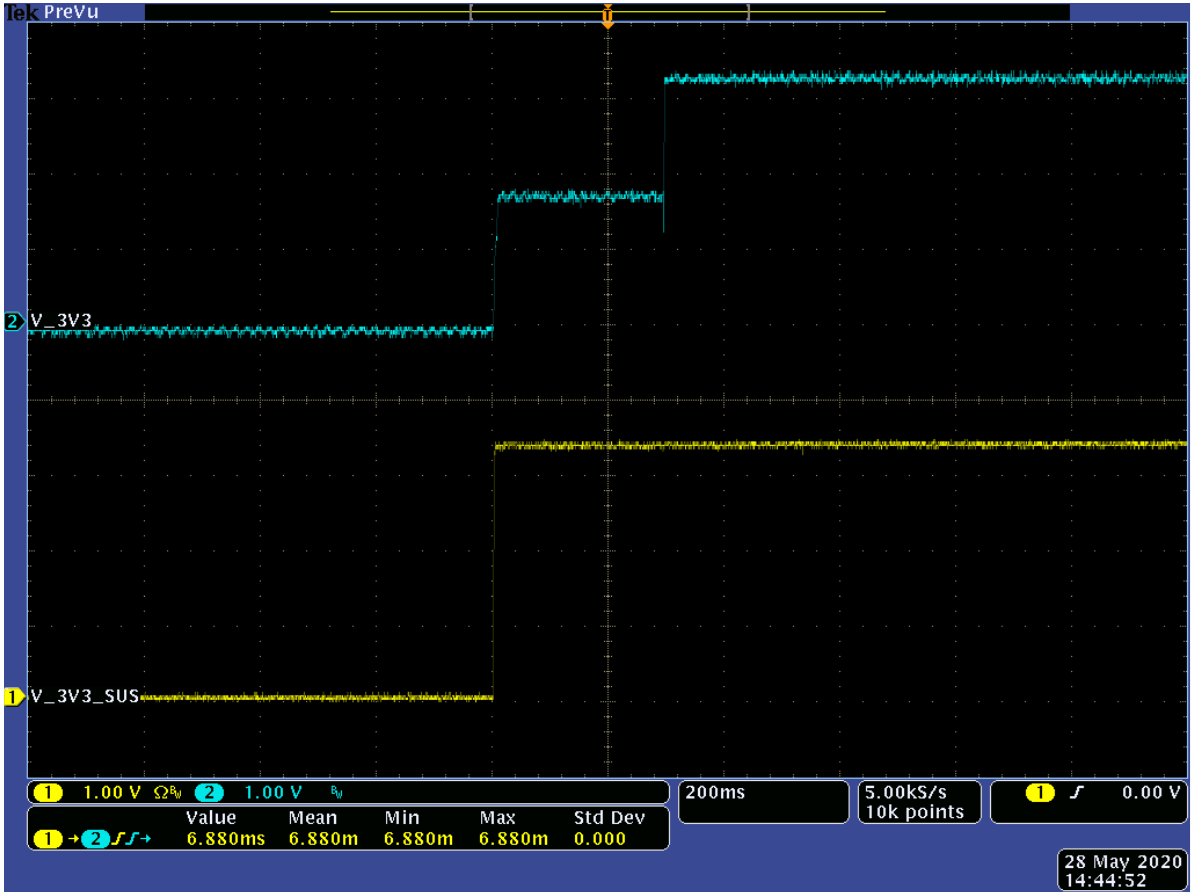
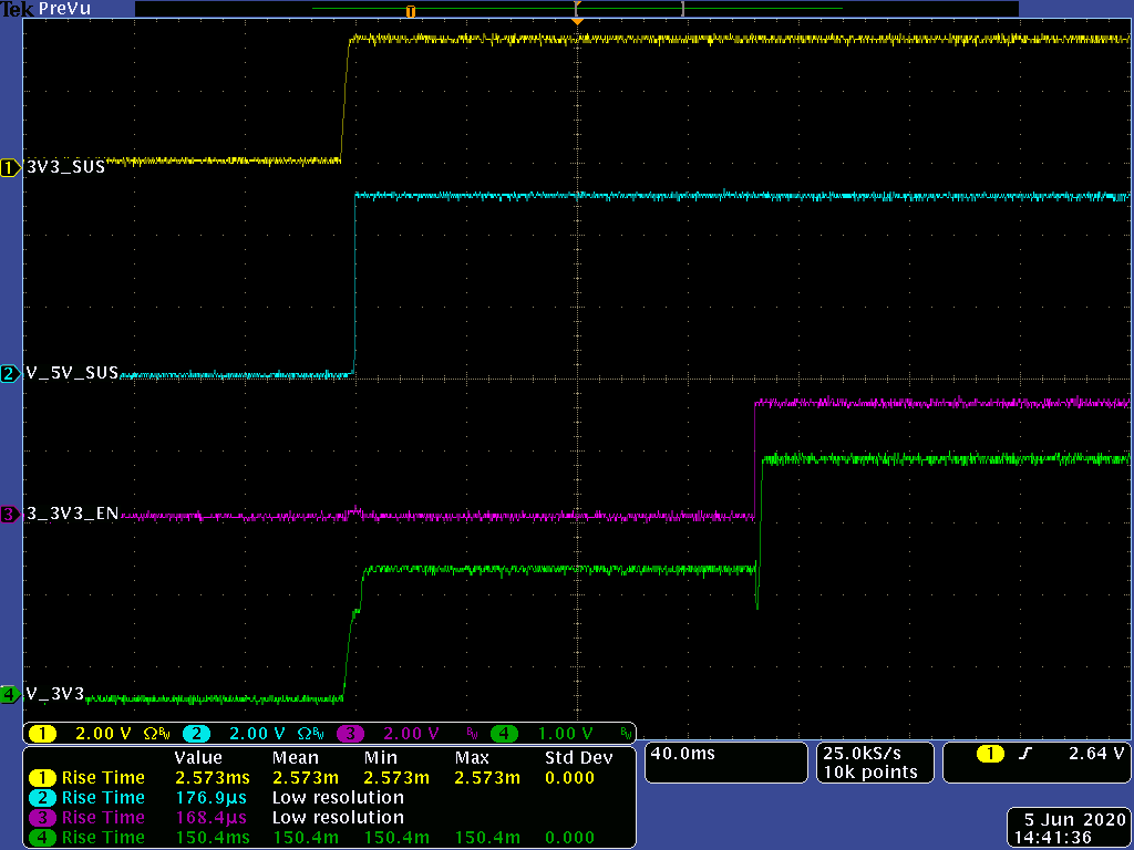
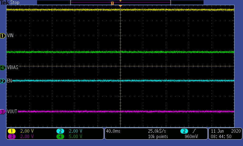
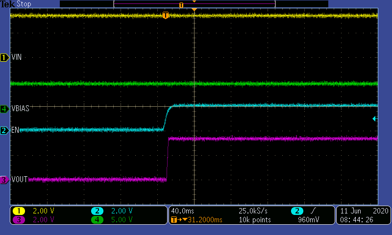
    This is not how the load switch should behave, so before we figure out a solution we need to find the root cause. Thank you for the scope shot with VIN, and VOUT, but would you be able to share a scope shot with VIN, VOUT, ON, and VBIAS signal during the switching event?

    Best regards,

    Andy Robles

  • hi andy 

    Please find the screenshots as requested.

  • Hi Vineeth,

    I will be ordering some EVM units to replicate the error we're seeing in order to find a solution. I'll be able to report results back by the end of next week after EVM boards arrive and I'm able to take some measurements.

    Best regards,

    Andy Robles

  • Hi Vineeth,

    Using the EVM for the TPS22969 I was able to run some tests. By applying 3.3V at VIN and 5V on VBIAS I observed the following behavior from the EVM:

    Once I toggled the enable pin the IC behaved as described by the datasheet:

    Testing the IC with the EVM I can confirm that the 1.8V seen on the output of the system is not coming from the IC, but may be getting coupled from something else in the system.

    Judging from the behavior of the 1.8V dropping to 0.8V when VBIAS is changed means that somehow the two are related. Is there anything else connected to the output of the load switch that could be coupling the 1.8V from the VBIAS voltage rail?

    Best regards,

    Andy Robles