


Other Parts Discussed in Thread: TPS61235P
Hello engineers,
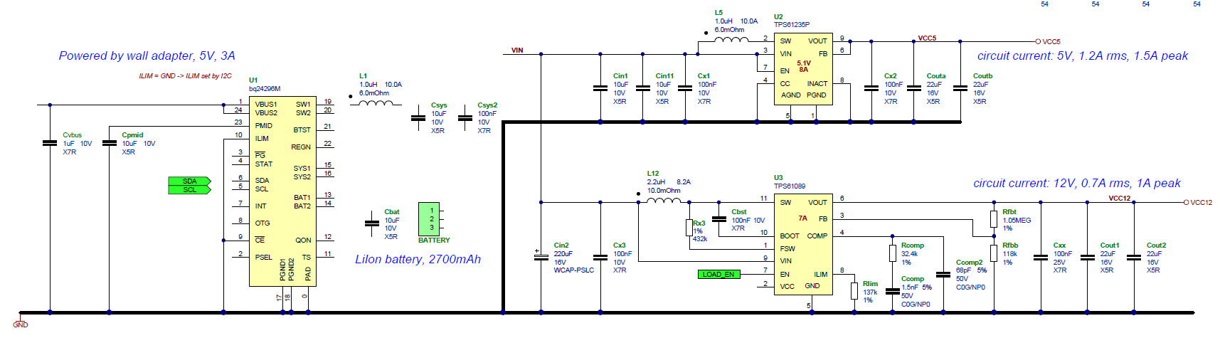
I'm currently developing a PSU for a low-cost portable equipment, I've drawn a preliminary schematic using the three chips in the title; please take a look at the (incomplete) schematic below:
Requirements and specs:
- the unit can be powered from wall adapter (5V, 3A) or the internal battery pack (2700 mAh to 10000 mAh, will test during prototyping)
- when the unit is powered by the wall adapter, circuit have to be powered AND the battery must recharge (with usual IC's powerpath limits)
- 12V line power is controlled by "ENABLE" pin (for power saving)
- I need 5V @ 1.2A RMS / 1.5A peak AND 12V @ 0.7A RMS / 1A peak
- Alternatively, instead of 5V, the output can be 3.3V @ 1.9A RMS / 2.3A peak
There's a MPU which can control bq24296M's parameters via I2C
The question is: there is a way to simplify schematic / use different chips for COST SAVING?
I'm specifically lookin' at avoiding the double conversion for 5V (3.3V) line - one by bq24296M and one by TPS61235P.
An ideal way would be to have the battery charger / controller chip which outputs 5V (3.3V) directly, but I'm searchin' thru tens of datasheets from days and found nothing. The nearest function is the OTG 5.1V output, but I can't use it in this application.
There's a lot of space on PCB so larger components aren't a problem.
Total efficiency should be around 90% or more.
Thank you very much, best regards.
- Marco Dassi
