This thread has been locked.

If you have a related question, please click the "Ask a related question" button in the top right corner. The newly created question will be automatically linked to this question.

TPS62826: 100% Duty Cycle for Step-down converter

Part Number: TPS62826

I am looking at your TPS62826 step-down converter and have a unique situation. In most instances I need to step down the voltage of the input voltage, but there may be a configuration where I want to force the SW output to equal that of the Vin input. Regardless of the whether the output voltage is stepped down or not, I need the output voltage to be switched (i.e. use the EN signal) which is why I would the device in rather than bypassing it with a jumper or zero ohm resistor.

Since the TPS6282x series is capable of 100% duty cycle according to the datasheet, I was hoping to force the TPS62826 to act as a simple FET switch in this instance. Would this be possible if R1 in Figure 6 of the datasheet is simply omitted? Assuming the TPS62826 can be forced to act as just a switch (100% duty cycle), can the L1 inductor be changed to a zero ohm resistor to reduce the DC losses when operating in this manner?

  • Hi Rich,

    I recommend to use a step-down converter in an application that requires a voltage step-down. To act as a simple FET switch, we have several load switch in our portfolio which might be of interest to you. The configuration that you explained is not the recommended way of operating a step-down converter. 

    I would still be curious to know the reason for using a DC-DC step down converter for such an application.

    Regards,

    Febin

  • Febin,

       Thanks for the quick reply.  I wanted to use the TPS62826 in an application that requires step down conversion from a 3.3 V rail in most instances that also needs to be properly sequenced during power up.  The TPS62826 fits these requirements nicely and also comes in a small package.  There is also a very likely possibility that the hardware may need to be reconfigured and some step down voltages may need to be changed.  Changing the step down voltage would easily accomplished by changing the R1/R2 ratio.

    ...BUT...

    The hardware reconfiguration may necessitate use of the 3.3 V input rail directly with no step down.  Since it is desirable to re-purpose an existing design by simply changing a few components, that would be the goal.  The TPS62826 datasheet indicates it supports 100% duty cycle, has an enable input and a high side FET with a low RDS resistance.  I was hoping that with some minor component changes it could be used as a simple FET switch in the scenario described.  Its primary use in the design would be that of a step down converter and in some rare instances as a simple FET switch.

    With this in mind, can the TPS62826 be forced into the 100% mode by omitting R1?  And if so, can L1 be changed to a zero ohm resistor to further reduce the voltage drop?

    -Thanks-

  • Hi Rich,

    I really appreciate your efforts to provide such a detailed explanation. This is really interesting. I understand the purpose. 

    Unfortunately, a DC-DC converter cannot be operated this way- L1 be changed to a zero ohm resistor and omitting R1. You will have to look for a load switch for the above requirement.

    I hope you will be fine to close this thread now. Please let me know if I can help you further.

    Regards,

    Febin

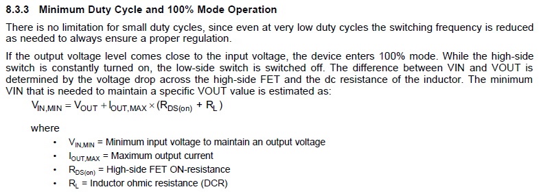
  • Let me ask a variant of the question.  Based on the following section of the data sheet:

    is the TPS62826 capable of sustained operation in the 100% mode of operation? Instead of simply removing R1, what if its value is increased such that the R1/R2 ratio drives (on paper) the Vout voltage higher than the Vin voltage resulting in a 100% duty cycle.  TI touts '100% duty cycle for lowest dropout' in the features section and specifically addresses it in section 8.3.3.

    Assuming the L1 inductor is left in place and the R1/R2 ratio forces the device into the 100% mode, can the TPS62826 operate is this mode for long periods of time or indefinitely?  

  • Hi Rich,

    The feedback resistor divider- R1 & R2 determines the output voltage. If you change R1 or R2, it changes the output voltage but if the ratio is unchanged then you should get the same output voltage. 

    The device can be operated in 100% mode as long as Tj is not over Tj_max. Because Rds-on is dependent on VIN and Tj. Referring to the above equation (for Vin,min) you will be able to calculate efficiency at maximum Rds-on at any operating temperature in 100% mode.

    Additionally, I would like to share an interesting Application note that explains '100% mode operation in DC-DC converters'. 

    http://www.ti.com/lit/an/slyt747/slyt747.pdf?ts=1591352497557

    Regards,

    Febin

  • Febin,

       Including the link to the 100% mode article was very helpful.  I should have mentioned that the load will be light in the application I would be looking to feed the 3.3V rail through.

    Thanks for your help.