This thread has been locked.

If you have a related question, please click the "Ask a related question" button in the top right corner. The newly created question will be automatically linked to this question.

UCC256402: Loop gain equations for the UCC256402

Part Number: UCC256402
Other Parts Discussed in Thread: TL431, UCC25640EVM-020

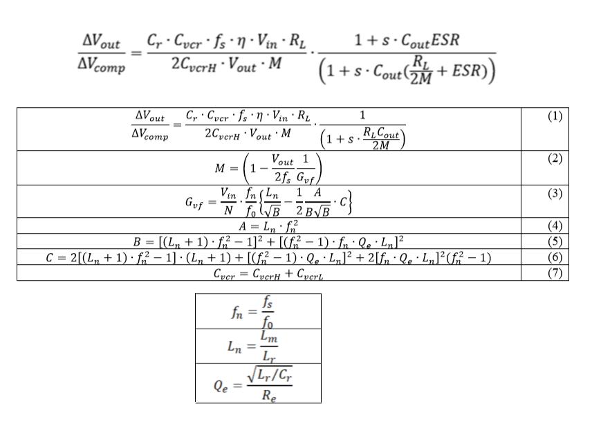
I am missing the loop gain equations for the UCC256402, like whats the formula for Ires/Vfb? - there is a detailed design procedure in the datasheet, but it doesnt mention anything about loop gain?

like the components around the TL431 - how's the pole/zero selected?

best regards

Kim N Madsen

  • Hi,

    Can you clarify what is Ires in your question?Is it the resonant current? 

  • Hi Hong Huang

    the datasheet claims: "Hybrid hysteretic control (HHC) – Best-in-class transient response" - but there is no detailed design how to get to the "best in class transient responce"

    lets take the eval board UCC25640EVM-020 as example.

    user guide: : SLUUBX3B

    whats the gain from FB node to resonant current in C1/C17?

    the compensation circuit around TL431 gives a zero: R22/C26, a pole C25/R22, the mid frequency gain R19/R22 - those are selected to give a certain responce - but its not shown in detail how? the measured loop gain is shown, but not the model for it or calculations to get to it.

    is there a ac-pspice model? or even a transient model

    best regards

    kim

  • Hi,

    On HHC, can you review the datasheet section 8.3.1? HHC design is related to VCR. 

    On the feedback loop compensation design, I am contacting the designer of the EVM to know how the EVM feedback loop compensation is designed. I will provide that after I get it.

  • Hi Hong Huang

    yes section 8.3.1 talks about the design of the HHC, but there are no equation for gain from VCOMP (FB) to the resonant current. 

    it states:

    "In summary, HHC solves the following problems: • Help LLC converters achieve superior load transient and line transient • Changes the small-signal transfer function to a first order system to easily achieve very high bandwidth • Inherently stable via frequency compensation"

    so if its a first order system, there should be a equation from the FB node to current in the resonant circuit.

    it will be good to get the EVM feedback loop design.

    thanks

    kim

  • hi Hong Huang

    is there a spice model available for the UCC256402?

    rgds

    kim n madsen

  • Hi,

    We do not have a Spice model. But we have a Simplis model

    https://www.ti.com/lit/zip/slum684

    The first order system model based on our analytical development is like the below. In general, Type II compensation is ok to use to compensate a first order system.

    The EVM uses a Type III compensation to make performance adjustment such as to achieve wider bandwidth.

  • Hi Hong Huang

    Thank you for the link to the simplis model - will there be a TI-spice model? we dont have the Simplis program.

    where you able to get the EVM loop design?

    Best regards

    kim 

  • Hi,

    There is no plan for TI-Spice model from design team. You may send a request to your local TI sales to request the TI-Spice model. The sales will help to drive this.

    The loop design is currently based on the formulas I sent to you. There will be an addition to the current excel spread sheet calculator on the loop design. But this is not available now.