This thread has been locked.

If you have a related question, please click the "Ask a related question" button in the top right corner. The newly created question will be automatically linked to this question.

BQ34110: BQ34110 not reporting correct RSOC, Average Time to Empty, Average time to Full and Remaining, Remaining Capacity , values during discharge. Values are ok during charge

Part Number: BQ34110
Other Parts Discussed in Thread: BQSTUDIO, , GPCCEDV

Hi,

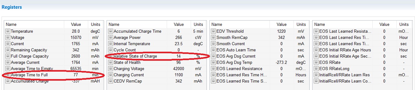
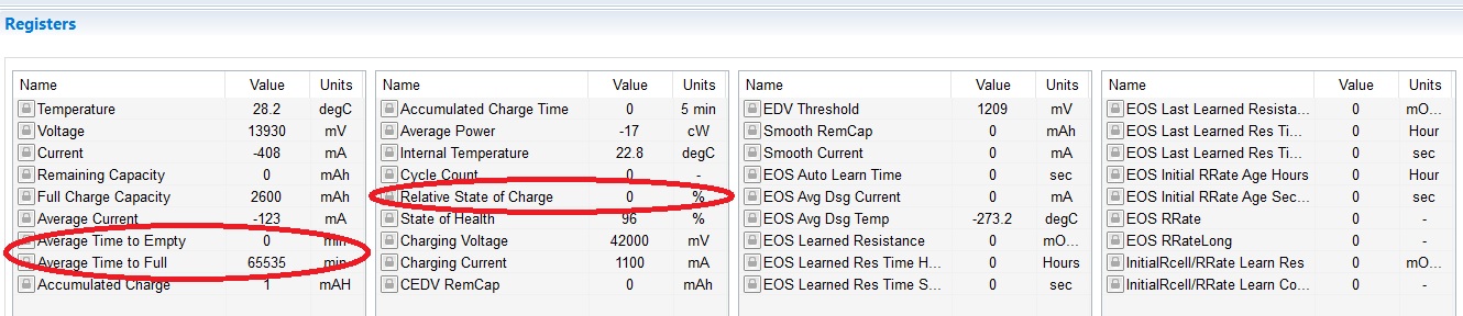
Hope this finds you well. I am working on a 10cell NiMH application and am having issues during discharge,. Specifically, the RSOC value seems ok during charge, but goes to zero percent during discharge. Similarly, Average time to full and and average time to empty report reasonable data in bqstudio during charge, but report values of 65535 during discharge.

I have not yet performed the calibration CEDV 6-cycles to obtain coefficients yet. Is that necessary for this particular issue?

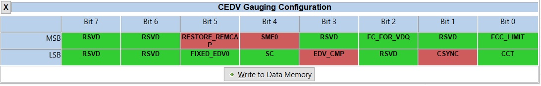
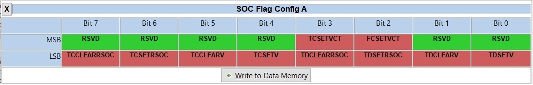
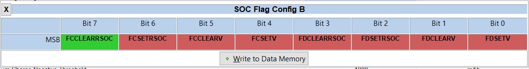
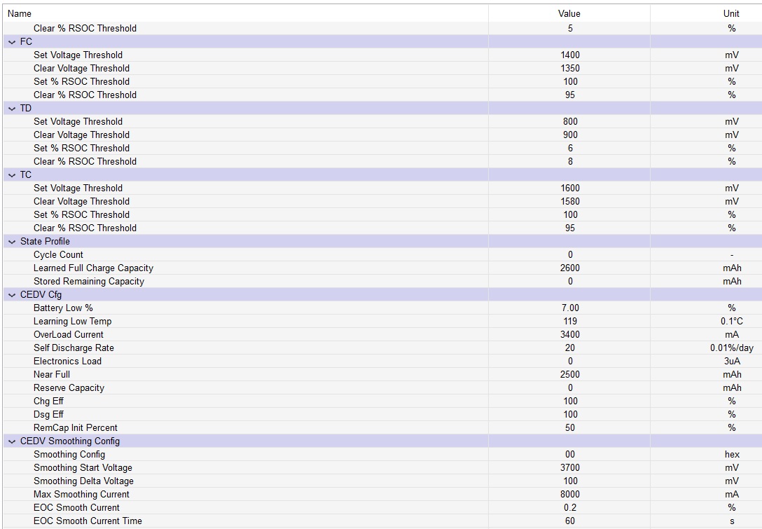
I have attached my dataflash settings in a file to this post. I have also posted logs from a charge and discharge cycle. 

Please advise what settings should be modified,  and if you would like any more information from me to help with this. discharge_cycle.logbq_charge_cycle.xlsxand thank you!

Best Regards,

Brian 

bq34110_NiMH_settings.gg.csv 

  • Hi Brian,

    I would suggest you use the tool below to obtain the proper Compensated End of Discharge Voltage (CEDV) coefficients. 

    http://www.ti.com/tool/GPCCEDV

    Andy

  • Hi Andy,

    Thank you very much for your quick reply!

    Is this GPCCEDV step absolutely necessary for my particular case? Or will it just make the gauging more accurate? 

    Best Regards,

    Brian

  • You do need to characterize the battery with GPCCEDV.  You cannot simply use default settings.

    Andy

  • Hi Andy,

    Thank you for your reply, much appreciated.  I followed your advice and characterized our battery with the GPCCEDV tool as was able to obtain coefficients from TI yesterday. They were as follows: 

    GPC CEDV tool, rev=53
    Configuration used in present fit
    ProcessingType=1
    NumCellSeries=10
    CellTermV=1000
    LearnSOC%=7
    FitMaxSOC%=9
    FitMinSOC%=3
    ChemType=2
    ElapsedTimeColumn=0
    VoltageColumn=1
    TemperatureColumn=2
    CurrentColumn=3

    CEDV parameters resulting from the fit. If EDVV bit is set to 1, EMF and EDVR0 have to be multiplied by the number of serial cells when written to data flash

    EMF 1258
    EDVC0 376
    EDVC1 0
    EDVR1 1
    EDVR0 833
    EDVT0 4763
    EDVTC 9
    VOC75 12975
    VOC50 12722
    VOC25 12382


    Recommended SOC deviation tolerance at EDV2 point is < 5% for low temperature and <3% for room and high temperature

    Deviations for this set of parameters are given below for each file

    file SOC error, % pass
    roomtemp_lowrate.csv -3.03082293829607 0
    roomtemp_highrate.csv 3.45463650778249 0
    hightemp_lowrate.csv -0.713556303124196 1
    hightemp_highrate.csv -1.35672852800538 1
    lowtemp_lowrate.csv 0.710489549883981 1
    lowtemp_highrate.csv -4.39401573621694 1

    Warning: Deviation is above recommended level. Retry the fit with different settings, or proceed on your own risk if the accuracy is acceptable for your application

    -----

    I am aware that some of the deviations are high in these particular results. We are going to run the calculations again with more cells soon. The main issue is that this did not correct the original issue of losing RSOC percentage during discharge at .5C. The percentage drops to 0% during discharge still!

    Can you please help me find out what parameter(s) need to be changed in order for RSOC to not go to zero during discharge? And please let me know if there is more information I can provide Thanks again.

    Here is my CEDV Gauging Configuration: 

    Here is my SOC Flag Config A:

    Here is my SOC Flag Config B:

    Here are two images showing My gas gauging Data Memory contents:

    And finally, here is before and after. Image 1 shows decent RSOC tracking during a charge:

    And here is the issue I am trying to solve. during discharge, The bq loses the values of average time to full and relative state of charge:

    PS: 

    Here is my gg csv settings as of today:

    * Texas Instruments Data Flash File
    * File created Tue Jun 16 11:57:34 2020
    *
    * Device Number 110
    * Firmware Version 0.02
    * Build Number 9
    * Order Number 0
    *
    * bqz Device Number 110
    * bqz Firmware Version 0.02
    * bqz Build Number 9
    *
    * Field Order: Class name  Subclass name  Parameter name  Parameter Value  Display Units
    Calibration Data CC Gain 14.151 mOhm
    Calibration Data CC Delta 14.299 mOhm
    Calibration Data CC Offset -44.13 mA
    Calibration Data Board Offset 0 uA
    Calibration Data Int Temp Offset 0 °C
    Calibration Data Ext Temp Offset 0.5 °C
    Calibration Data Pack V Offset 0 mV
    Calibration Data Voltage Divider 40300 mV
    Calibration Temp Model Int Coeff 1 0 Num
    Calibration Temp Model Int Coeff 2 0 Num
    Calibration Temp Model Int Coeff 3 -12324 Num
    Calibration Temp Model Int Coeff 4 613.1 degK
    Calibration Temp Model Int Min AD 0 -
    Calibration Temp Model Int Max Temp 6131 0.1degK
    Calibration Temp Model Ext Coeff 1 20982 Num
    Calibration Temp Model Ext Coeff 2 -13836 Num
    Calibration Temp Model Ext Coeff 3 5202 Num
    Calibration Temp Model Ext Coeff 4 233.7 degK
    Calibration Temp Model Ext Min AD 12909 -
    Calibration Temp Model Vcomp Coeff 1 0 Num
    Calibration Temp Model Vcomp Coeff 2 14902 Num
    Calibration Temp Model Vcomp Coeff 3 -623 Num
    Calibration Temp Model Vcomp Coeff 4 37 Num
    Calibration Temp Model Vcomp Input Multiplier 48 Num
    Calibration Temp Model Vcomp Output Divisor 256 Num
    Calibration Current Filter 239 Num
    Calibration Current Deadband 5 mA
    Calibration Current CC Deadband 34 149nV
    Charger Control Charge Inhibit Cfg Chg Inhibit Temp Low 0 °C
    Charger Control Charge Inhibit Cfg Chg Inhibit Temp High 45 °C
    Charger Control Charge Inhibit Cfg Temp Hys 5 °C
    Charger Control JEITA Temperature T1 Temp 0 °C
    Charger Control JEITA Temperature T2 Temp 10 °C
    Charger Control JEITA Temperature T3 Temp 45 °C
    Charger Control JEITA Temperature T4 Temp 55 °C
    Charger Control JEITA Temperature Charge Current T1-T2 300 mA
    Charger Control JEITA Temperature Charge Current T2-T3 1100 mA
    Charger Control JEITA Temperature Charge Current T3-T4 660 mA
    Charger Control JEITA Temperature Charge Voltage T1-T2 4100 mV
    Charger Control JEITA Temperature Charge Voltage T2-T3 4200 mV
    Charger Control JEITA Temperature Charge Voltage T3-T4 4100 mA
    Charger Control Charge Termination Maintenance Current 0 mA
    Charger Control Charge Termination Taper Current 100 mA
    Charger Control Charge Termination Minimum Taper Capacity 25 0.01mAh
    Charger Control Charge Termination Taper Voltage 100 mV
    Charger Control Charge Termination Current Taper Window 40 s
    Charger Control WHr Charge Termination Max Charge Voltage 4000 mV
    Charger Control WHr Charge Termination WHr CV Step 50 mV
    Charger Control WHr Charge Termination WHr Termination Capacity 1100 mAh
    Charger Control WHr Charge Termination FC WHr Clear 1000 mAh
    Charger Control NiMH Charge Termination Delta Temperature 3 °C
    Charger Control NiMH Charge Termination Delta Temperature Time 100 s
    Charger Control NiMH Charge Termination Holdoff Time 180 s
    Charger Control NiMH Charge Termination Holdoff Current 240 mA
    Charger Control NiMH Charge Termination Holdoff Temperature 25 °C
    Charger Control NiMH Charge Termination Cell Negative Delta Voltage 17 mV
    Charger Control NiMH Charge Termination Cell Negative Delta Time 16 s
    Charger Control NiMH Charge Termination Cell Negative Delta Qual Voltage 3600 mV
    Charger Control Learned Charge Voltage Last Charge Voltage T1-T2 4100 mV
    Charger Control Learned Charge Voltage Last Charge Voltage T2-T3 4200 mV
    Charger Control Learned Charge Voltage Last Charge Voltage T3-T4 4100 mV
    Charger Control Charge Level Control Charge Voltage Level A 3900 mV
    Charger Control Charge Level Control Charge Voltage Level B 3950 mV
    Charger Control Charge Level Control Charge Voltage Level C 4000 mV
    Charger Control Charge Level Control Charge Voltage Level D 4050 mV
    Charger Control Charge Level Control Charge Voltage Level E 4100 mV
    Charger Control Charge Level Control Charge Voltage Level F 4150 mV
    Charger Control Charge Level Control Charge Voltage Level G 4200 mV
    Charger Control Charge Level Control Charge Voltage Level H 4250 mV
    Settings Configuration Direct Charge Pin Control 0 hex
    Settings Configuration Charge Level Pin Control 0 hex
    Settings Configuration Pin Control Config 10 hex
    Settings Configuration Alert1_0 Config 0 hex
    Settings Configuration Alert1_1 Config 0 hex
    Settings Configuration Alert1_2 Config 0 hex
    Settings Configuration Alert1_3 Config 0 hex
    Settings Configuration Alert1_4 Config 0 hex
    Settings Configuration Alert1_5 Config 0 hex
    Settings Configuration Alert1_6 Config 0 hex
    Settings Configuration Alert2_0 Config 0 hex
    Settings Configuration Alert2_1 Config 0 hex
    Settings Configuration Alert2_2 Config 0 hex
    Settings Configuration Alert2_3 Config 0 hex
    Settings Configuration Alert2_4 Config 0 hex
    Settings Configuration Alert2_5 Config 0 hex
    Settings Configuration Alert2_6 Config 0 hex
    Settings Configuration SOC Flag Config A 0cff hex
    Settings Configuration SOC Flag Config B 7f hex
    Settings Configuration CEDV Gauging Configuration 300a hex
    Settings Configuration EOS Configuration 1 hex
    Settings BLT Init Discharge Set 150 mAh
    Settings BLT Init Charge Set 2500 mAh
    Settings Accumulated Charge Accum Charge Positive Threshold 1000 mAh
    Settings Accumulated Charge Accum Charge Negative Threshold 1000 mAh
    Settings Manufacturing Mfg Status Init 3 hex
    Safety OTC OT Chg 55 °C
    Safety OTC OT Chg Time 2 s
    Safety OTC OT Chg Recovery 50 °C
    Safety OTD OT Dsg 60 °C
    Safety OTD OT Dsg Time 2 s
    Safety OTD OT Dsg Recovery 55 °C
    Safety UTC UT Chg 0 °C
    Safety UTC UT Chg Time 2 s
    Safety UTC UT Chg Recovery 5 °C
    Safety UTD UT Dsg 0 °C
    Safety UTD UT Dsg Time 2 s
    Safety UTD UT Dsg Recovery 5 °C
    Safety BATLOW Battery Low Set Threshold 900 mV
    Safety BATLOW Battery Low Time 2 s
    Safety BATLOW Battery Low Clear Threshold 950 mV
    Safety BATHIGH Battery High Set Threshold 1500 mV
    Safety BATHIGH Battery High Time 2 s
    Safety BATHIGH Battery High Clear Threshold 1400 mV
    Safety SOCLOW SOC Low Threshold 10 %
    Safety SOCLOW SOC Low Recovery 30 %
    Configuration Registers Operation Config A 8004 hex
    Configuration Registers Device Type 110 Hex
    Configuration Registers Number of Series Cells 10 Num
    Configuration Power Flash Update OK Voltage 100 mV
    Configuration Power Sleep Current 10 mA
    Configuration Power Bus Low Time 5 s
    Configuration Power Offset Cal Inhibit Temp Low 5 °C
    Configuration Power Offset Cal Inhibit Temp High 45 °C
    Configuration Power Sleep Voltage Time 20 s
    Configuration Power Sleep Current Time 20 s
    Configuration Current Thresholds Discharge Detection Threshold 60 mA
    Configuration Current Thresholds Charge Detection Threshold 75 mA
    Configuration Current Thresholds Quit Current 40 mA
    Configuration Current Thresholds Discharge Relax Time 60 s
    Configuration Current Thresholds Charge Relax Time 60 s
    Configuration Current Thresholds Quit Relax Time 1 s
    Configuration Data Default Temperature 298.2 K
    Configuration Data Device Name bq34110 -
    Configuration Data Data Flash Version ffff -
    Configuration Data Serial Number 1 hex
    Configuration Data Manufacture Date 1/1/1980 Day + Mo*32 + (Yr -1980)*512
    Configuration Integrity Data DF Static Checksum 0 hex
    Configuration Integrity Data All DF Checksum 0 hex
    Configuration Integrity Data IF Checksum fbd3e090 hex
    Configuration Integrity Data Full Reset Counter 133 Num
    Configuration Integrity Data Reset Counter WD 0 Num
    System Data Manufacturer Data Manufacturer Info Block A01 0 Hex
    System Data Manufacturer Data Manufacturer Info Block A02 0 Hex
    System Data Manufacturer Data Manufacturer Info Block A03 0 Hex
    System Data Manufacturer Data Manufacturer Info Block A04 0 Hex
    System Data Manufacturer Data Manufacturer Info Block A05 0 Hex
    System Data Manufacturer Data Manufacturer Info Block A06 0 Hex
    System Data Manufacturer Data Manufacturer Info Block A07 0 Hex
    System Data Manufacturer Data Manufacturer Info Block A08 0 Hex
    System Data Manufacturer Data Manufacturer Info Block A09 0 Hex
    System Data Manufacturer Data Manufacturer Info Block A10 0 Hex
    System Data Manufacturer Data Manufacturer Info Block A11 0 Hex
    System Data Manufacturer Data Manufacturer Info Block A12 0 Hex
    System Data Manufacturer Data Manufacturer Info Block A13 0 Hex
    System Data Manufacturer Data Manufacturer Info Block A14 0 Hex
    System Data Manufacturer Data Manufacturer Info Block A15 0 Hex
    System Data Manufacturer Data Manufacturer Info Block A16 0 Hex
    System Data Manufacturer Data Manufacturer Info Block A17 0 Hex
    System Data Manufacturer Data Manufacturer Info Block A18 0 Hex
    System Data Manufacturer Data Manufacturer Info Block A19 0 Hex
    System Data Manufacturer Data Manufacturer Info Block A20 0 Hex
    System Data Manufacturer Data Manufacturer Info Block A21 0 Hex
    System Data Manufacturer Data Manufacturer Info Block A22 0 Hex
    System Data Manufacturer Data Manufacturer Info Block A23 0 Hex
    System Data Manufacturer Data Manufacturer Info Block A24 0 Hex
    System Data Manufacturer Data Manufacturer Info Block A25 0 Hex
    System Data Manufacturer Data Manufacturer Info Block A26 0 Hex
    System Data Manufacturer Data Manufacturer Info Block A27 0 Hex
    System Data Manufacturer Data Manufacturer Info Block A28 0 Hex
    System Data Manufacturer Data Manufacturer Info Block A29 0 Hex
    System Data Manufacturer Data Manufacturer Info Block A30 0 Hex
    System Data Manufacturer Data Manufacturer Info Block A31 0 Hex
    System Data Manufacturer Data Manufacturer Info Block A32 0 Hex
    Lifetimes Lifetime Resolution Temperature Resolution 1 C
    Lifetimes Lifetime Resolution Current Resolution 100 mA
    Lifetimes Lifetime Resolution Voltage Resolution 1 20mV
    Lifetimes Temperature Max Temperature 30 C
    Lifetimes Temperature Min Temperature 20 C
    Lifetimes Current Max Charge Current 1000 mA
    Lifetimes Current Max Discharge Current 1000 mA
    Lifetimes Voltage Max Pack Voltage 14000 20mV
    Lifetimes Voltage Min Pack Voltage 10000 20mV
    Gas Gauging CEDV Profile Design Capacity mAh 2700 mAh
    Gas Gauging CEDV Profile EMF 1258 -
    Gas Gauging CEDV Profile C0 149 -
    Gas Gauging CEDV Profile R0 833 -
    Gas Gauging CEDV Profile T0 4763 -
    Gas Gauging CEDV Profile R1 1 -
    Gas Gauging CEDV Profile TC 9 -
    Gas Gauging CEDV Profile C1 0 -
    Gas Gauging CEDV Profile Age Factor 0 -
    Gas Gauging CEDV Profile Fixed EDV 0 800 -
    Gas Gauging CEDV Profile EDV 0 Hold Time 1 s
    Gas Gauging CEDV Profile Fixed EDV 1 1100 -
    Gas Gauging CEDV Profile EDV 1 Hold Time 1 s
    Gas Gauging CEDV Profile Fixed EDV 2 1150 -
    Gas Gauging CEDV Profile EDV 2 Hold Time 1 s
    Gas Gauging CEDV Profile Voltage 0% DOD 4173 mV
    Gas Gauging CEDV Profile Voltage 10% DOD 4043 mV
    Gas Gauging CEDV Profile Voltage 20% DOD 3925 mV
    Gas Gauging CEDV Profile Voltage 30% DOD 3821 mV
    Gas Gauging CEDV Profile Voltage 40% DOD 3725 mV
    Gas Gauging CEDV Profile Voltage 50% DOD 3656 mV
    Gas Gauging CEDV Profile Voltage 60% DOD 3619 mV
    Gas Gauging CEDV Profile Voltage 70% DOD 3582 mV
    Gas Gauging CEDV Profile Voltage 80% DOD 3515 mV
    Gas Gauging CEDV Profile Voltage 90% DOD 3439 mV
    Gas Gauging CEDV Profile Voltage 100% DOD 2713 mV
    Gas Gauging Design Design Voltage 1400 mV
    Gas Gauging Cycle Cycle Count Percentage 90 %
    Gas Gauging FD Set Voltage Threshold 900 mV
    Gas Gauging FD Clear Voltage Threshold 1000 mV
    Gas Gauging FD Set % RSOC Threshold 0 %
    Gas Gauging FD Clear % RSOC Threshold 5 %
    Gas Gauging FC Set Voltage Threshold 1400 mV
    Gas Gauging FC Clear Voltage Threshold 1350 mV
    Gas Gauging FC Set % RSOC Threshold 100 %
    Gas Gauging FC Clear % RSOC Threshold 95 %
    Gas Gauging TD Set Voltage Threshold 800 mV
    Gas Gauging TD Clear Voltage Threshold 900 mV
    Gas Gauging TD Set % RSOC Threshold 6 %
    Gas Gauging TD Clear % RSOC Threshold 8 %
    Gas Gauging TC Set Voltage Threshold 1600 mV
    Gas Gauging TC Clear Voltage Threshold 1580 mV
    Gas Gauging TC Set % RSOC Threshold 100 %
    Gas Gauging TC Clear % RSOC Threshold 95 %
    Gas Gauging State Profile Cycle Count 0 -
    Gas Gauging State Profile Learned Full Charge Capacity 2600 mAh
    Gas Gauging State Profile Stored Remaining Capacity 0 mAh
    Gas Gauging CEDV Cfg Battery Low % 7 %
    Gas Gauging CEDV Cfg Learning Low Temp 119 0.1°C
    Gas Gauging CEDV Cfg OverLoad Current 3400 mA
    Gas Gauging CEDV Cfg Self Discharge Rate 20 0.01%/day
    Gas Gauging CEDV Cfg Electronics Load 0 3uA
    Gas Gauging CEDV Cfg Near Full 2500 mAh
    Gas Gauging CEDV Cfg Reserve Capacity 0 mAh
    Gas Gauging CEDV Cfg Chg Eff 100 %
    Gas Gauging CEDV Cfg Dsg Eff 100 %
    Gas Gauging CEDV Cfg RemCap Init Percent 50 %
    Gas Gauging CEDV Smoothing Config Smoothing Config 0 hex
    Gas Gauging CEDV Smoothing Config Smoothing Start Voltage 3700 mV
    Gas Gauging CEDV Smoothing Config Smoothing Delta Voltage 100 mV
    Gas Gauging CEDV Smoothing Config Max Smoothing Current 8000 mA
    Gas Gauging CEDV Smoothing Config EOC Smooth Current 0.2 %
    Gas Gauging CEDV Smoothing Config EOC Smooth Current Time 60 s
    End Of Service Resistance Learning Auto Learn Time 1500 Hours
    End Of Service Resistance Learning Auto Learn Retry Time 1 Hours
    End Of Service Resistance Learning Minimum Learn Time 750 Hours
    End Of Service Resistance Learning Alert-Warn Learn Time 750 Hours
    End Of Service Resistance Learning Initial Learn Pulse Number 1 Counts
    End Of Service Resistance Learning Learn Charge Voltage Delta 100 mV
    End Of Service Resistance Learning Learn Charge Time Limit 3600 s
    End Of Service Resistance Learning Learn Discharge Current 220 mA
    End Of Service Resistance Learning Learn Discharge Current Boundary 25 %
    End Of Service Resistance Learning Learn Discharge Time 500 s
    End Of Service Resistance Learning Learn Request Timeout 4 s
    End Of Service Resistance Learning Learn Min Temperature 10 1°C
    End Of Service Resistance Learning Learn Max Temperature 40 1°C
    End Of Service Resistance Learning Learn Target Temperature 25 1°C
    End Of Service Resistance Learning Rcell High Temp Coefficient 0 2^-16/0.1°C
    End Of Service Resistance Learning Rcell Low Temp Coefficient 0 2^-16/0.1°C
    End Of Service Direct Resistance Decision DRD Alert Level 45 %
    End Of Service Direct Resistance Decision DRD Alert Counts 3 Counts
    End Of Service Direct Resistance Decision DRD Warning Level 60 %
    End Of Service Direct Resistance Decision DRD Warning Counts 3 Counts
    End Of Service Direct Resistance Decision Initial Rcell 0 mOhm
    End Of Service Direct Resistance Decision Initial Rcell Learned 0 -
    End Of Service Resistance Slope Decision RSD Alert Level 15 %
    End Of Service Resistance Slope Decision RSD Alert Counts 3 Counts
    End Of Service Resistance Slope Decision RSD Warning Level 30 %
    End Of Service Resistance Slope Decision RSD Warning Counts 3 Counts
    End Of Service Resistance Slope Decision RSDL Alert Level 15 %
    End Of Service Resistance Slope Decision RSDL Warning Level 30 %
    End Of Service Resistance Slope Decision Initial RRate 0 -
    End Of Service Resistance Slope Decision Initial RRate Learned 0 -
    End Of Service Safety Status Warning Status 0 hex

    Best Regards,

    Brian 

  • Hello Brian,

    It looks like you need to configure some parameters in your GG file, the TD, TC, FC, and FD don't match your CEDV voltages. This will cause some of the errors in the RSOC reported because in you soc_config_a block you have selected the these bits to be triggered with RSOC or voltage.

    Also in your CEDV gauging config you have the EDV_CMP bit on which means even though you calculated your batteries specs with the tool, it still might not use them, it may be calculating its own values. See section 2.7.9 in the TRM.

    Make sure you follow the steps for calibration, for the RSOC to be reported accurately the gauge needs to know all your batteries specifications and when you want to terminate charge/discharge.

    Sincerely,

    Wyatt Keller