This thread has been locked.

If you have a related question, please click the "Ask a related question" button in the top right corner. The newly created question will be automatically linked to this question.

TPS54160: Oscillation on 5V output

Part Number: TPS54160
Other Parts Discussed in Thread: TPS5405EVM

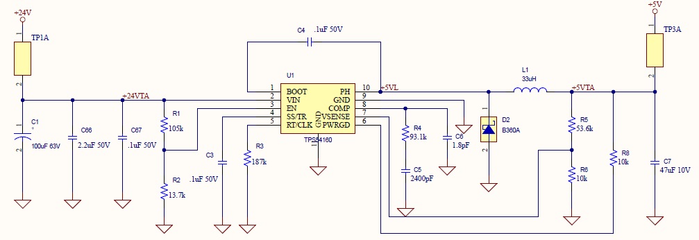
Hello. We are using a TPS54160 to step down from 24V to 5V. Under no load we are seeing an oscillation on the 5V output and the PWRGD signal is indicating a shutdown. We are attempting to debug both the schematic and layout design however have not been able to find any issue. 

See the regulator schematic below. Once TP3A is shorted, the output voltage will drop to around 1.6V. Using another 5V source to power TP3A.1 works without issue.

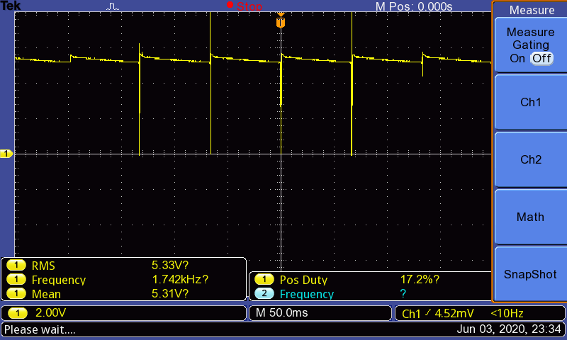
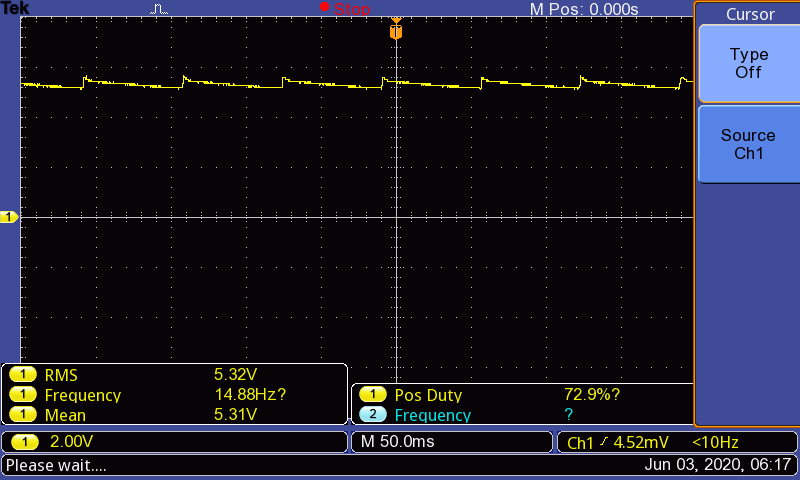
See 5V output with no load below. There is about a 500mV peak to peak oscillation at roughly 15Hz.

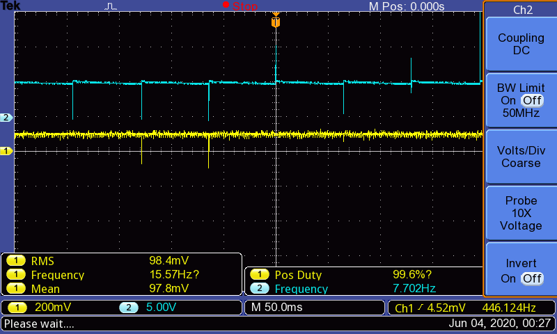
The PWRGD signal is indicating that there is a thermal, UVLO, or EN signal shutdown. The temperature of any junction related to TPS54160 does not exceed room temperature, the 24V input remains steady, and the EN signal is fixed at 2.8V in all conditions.

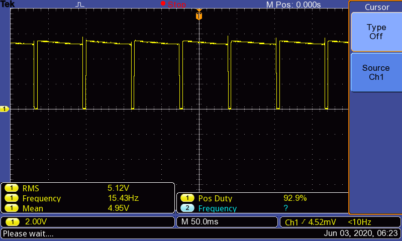
PWRGD signal (no load)

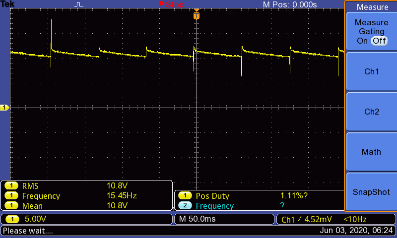
I am seeing similar oscillation on the bootstrap capacitor. This is on the BOOT pin (no load).

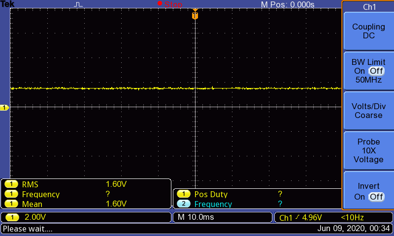
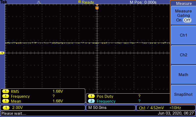
Once a load is applied, the voltage output drops.

Is there any input on what could be causing this behavior?

  • HI 

    I can't see the attached files, can you measure the SW waveform as well as inductor current so that we can identify the issue?

    Thanks

  • Hi Daniel,

    It looks like the schematic didn't come through. See below.

    I assume by SW waveform you are referring to PH (pin 10). See this waveform below.

    Also the current through the inductor is below (CH1). This is done using a 1mV/10mA current probe. It is along PH voltage (CH2).

    Thank you for your time on this.

  • Hi 

    thank you for sharing. the PH waveform shows when high side mosfet turn on, the PH=VIn, so

    the first PH waveform shows the input at no load is around 6V, 

    the second PH waveform shows the input voltage is down to 5V.

    can you check the whether there is a large resistor make the voltage drop?

    Thanks

  • Hi Daniel,

    I would like to clarify. The input on pin VIN (pin 2) is 24V. There is no deviation on the 24V under any condition. 

    Both graphs sent are the PH signal (pin 10) under no load. Between shut downs, the PH signal will move from around 5.4V max to around 4.8V. Below is a zoomed in view of the PH signal during the shutdown and there is substantial noise with spikes up to VIN (24V). 

    I will explore any connection between PH and VIN. The schematic is clean however I will need to explore the layout. Let me know if there is any other guidance. Thanks.

  • Hi Daniel,

    I have confirmed there is no path from PH to VIN. With TPS54160 and L1 removed, PH to VIN is open. When measuring resistance at +5VTA net to +24VTA net, the resistance is about 180k ohm which is expected (path through R1, R2, R6, and R5).

    Do you have any other guidance on what may be causing the instability?

  • HI

    can you help change C5 to 4.7nF and R4 to 51K see any improvement , if it improved, it looks loop isseu, If not, it is better to have SW waveform when you shorted the TP3A see what happened.

    Thanks

  • Hi Daniel,

    Updating C5 and R4 had no impact. The waveform on the 5V output persists.

    When closing TP3A the voltage output will still drop to 1.6V. Using an external +5V supply to supply TP3A.1 will work without issue. Here are a few scopes when TP3A is closed.

    +5VTA Net (after inductor) with TP3A is closed:

    PH (pin 10) when TP3A is closed:

    Closer view of PH (pin 10)

    To work around this issue we have using a TPS5405EVM board. I route the 24V to the TPS5405EVM board and then route the 5V output to TP3A.1. This works well so I believe the problem lies within our TPS54160 circuit. Let me know your thoughts. 


  • HI

    from the schematic, I don't see the issue. do you know the inductor's saturation current or do you have the inductor current waveform?

    if you have TPS54160EVM, you can try to connect to TP3A.1, see any different with your circuit.

    from the waveform, the chip work at DCM statues, and can you connect the external eload to see the output changes?

    Thanks

  • Hi Daniel,

    We were able to locate a different board that we designed some years ago with a TPS54160. Schematic are identical between the two boards. We did connect the 5V output to TP3A.1 and it worked well.

    I believe the issue is with the layout. The connections match the schematic but perhaps the placement is causing instability. Is it possible to send over Gerber file for review?

    Also the inductor we use is Vishay IHLP3232DZER330M11. Saturation current 3.2A.

  • Hi 

    Yes, I can check the Gerber.  

    thanks

  • Hi Daniel,

    Is there an email I can send it to? I would prefer not to post our Gerber on the forum.

  • Hi

    pls send to

    daniel-li@ti.com