This thread has been locked.

If you have a related question, please click the "Ask a related question" button in the top right corner. The newly created question will be automatically linked to this question.

TPS63030EVM-658: Very poor efficiency using EVM....

Part Number: TPS63030EVM-658
Other Parts Discussed in Thread: TPS63030, , TPS63060, TPS61030

I am using the TPS63030EVM-658 as an evaluation method for an LED system (driving 4 white LEDs in parallel).  I have noted in testing that the TPS63030 efficiency is really bad, on the order of 60% best case, when using the TPS63030EVM-658 board.   This has been duplicated across multiple test runs.   The only modification to the board was removal of R6 to allow current measurement.   

Becasuse I was concerned that the part couldn't handle the current, having run into this on other TI parts, I spun my own board using the TPS63060 using a similar scheme, albeit with some efficiency improvements.  The results are clear that the TPS63060 (or my design) is far superior to that on the EVM.  Here are the discharge curves for a single Li-Ion 18650 cell.

Discharge_curves.docx

Any thoughts on causes for this?   I'm happy to try another board if TI will provide it.   

  • HI Jon:

    Thanks for reaching out. May you share more details about the Vin, Vout and load condition with me? I afraid it may exceed the TPS63030's capability. 

    And may I know how you test the efficiency? Using a current measurement may bring additional voltage drop. 

  • As stated in my original post, the power source for testing was a single 18650 Li-ion cell, so the discharge was over the range of approximately 4.2V to 2.5V.  I deliberately allowed the cell to fully discharge since part of the data collected was to capture the entire discharge curve to assess a cut-off point to assess single-use life versus cycle life for the battery. 

    Vout is per the design of the EVM, so a fixed continuous current of 350mA (my EVM actually delivers about 355mA) feeding a diode.  I've done testing using both the on-board Osram part, as well as by placing 4 Cree LEDs at the output pins (with R6 removed).  The output configuration has not affected the results.  i'm seeing the buck-boost typically regulating at around 3.3 - 3.4V.    

    Current measurements are done using 10 mOhm resistors and data is collected at set intervals (i've done anywhere from every 5 seconds to every 30 seconds) using a data acquisition system.  I have done both high side and low side sensing without any notable change in results.

    Keep in mind that my design using the TPS63060, using the exact same input/output configuration (18650 cell driving a fixed current output at ~350mA) gives results that are much more in-line with expectations as shown in the attached doc.  The increased cost on this part and surrounding devices make this a very unattractive solution for what ultimately needs to be a low-cost device.   

    What i'm trying to determine is if the results are due to limitations in the TPS63030, as you stated.  This then begs the question why TI would have a demo board which exceeds the capabilities of the part, and why the efficiency graph in the datasheet is so inaccurate.   I find this option unlikely.   

    Alternately, there is something inherently wrong with my EVM board.  TI refuses to allow returns/replacement of the board.  They are happy to sell me another one, of course.

    Thoughts?

    Efficiency_Curve.docx    


  • Hi John:

    Sorry for keeping you waiting as it's so busy last week. 

    If the Vout is around 3.3-3.4V, it's within the TPS63030 capability. 

    And for the curve you measured, may I know your setup. You mentioned it's same for TPS63060, but I'll try to run it in my lab.

    I'll recommend you use a DC power supply as the input source, and measure the R3  in EVM can get the LED current.  It's better if you still have the LED in original board, to keep the min external factors.

  • I'm honestly not sure what more I can tell you on the setup for the TPS63030.  The configuration is the TI EVM board, TPS63030EVM-658, with R6 removed so that I can use an external load.  When using an external load, I take the current at either  side of J4 to the load.  Measuring the voltage across J4 gives me Vf on my diode, and we know the LED RTN side is sitting at 500mV above ground.  If it wasn't, my measured current would be off, and it's dead on (within 1%) of what is expected.   I can measure the current at R3 as well certainly, but there is nothing new to learn there since I already know that I see 181mV (across 0.51 Ohms) which is 355mA.  Again, the numbers on the output are right on what I expect, so it's not an issue with load since it regulates perfectly fine down below 3V on Vin.    

    The testing has been done using a power supply as well.  I'll see about getting a table of results thrown together since I don't have that right now.  The biggest clue in this is not to look at the load, but the input current to the board.  I'm putting 4V into the board and seeing it pull ~450mA (so 1.8W).  The load is about 1.2W (3.4V at 355mA), yielding an efficiency is about 67%.   If you test it in your lab, you literally have to do nothing except plug the board in and measure supply current since the rest of the math is already done.  I'd expect to see no more than 350mA with at 4V.  If you have more, than either the EVM has a design issue or the datasheet on the TP63030 is inaccurate.           

    My design with the TPS63060 is proprietary, so I can't post it on a public forum.  But, the short version is that it very closely matches the EVM, but uses a modified feedback configuration to allow me to control the LED current and to make the voltage reference more efficient.    That design really isn't important, since I'm not questioning that part or the design.  My efficiency graph for the TPS63060 looks very much like the datasheet.  So, the only reason the TPS63060 matters at all is to demonstrate that the problem is NOT in my test setup.

    But, if you think I can design a circuit around the TPS63060 that's tests at being 30% more efficient than the EVM design on the TPS63030, I appreciate your confidence in my design skills.  I think the much more sensible explanation is that something isn't right with my board.          

    This is really very simple.  My EVM board is pulling much current than it should need to maintain the load, so either the board itself or something inherent in the design (component selection?) is causing issues.  To get a replacement, I need approval via posting in this forum.       

  • Here is the data you requested.  

    EVM Board:

    63030 Vin 63030 In PowerIn 63030 Vout 63030 ILoad PowerOut Efficiency
    2.80 1189.25 3329.9 3.395 356.18 1209.15 36.31%
    3.00 910.972 2732.916 3.385 356.19 1205.78 44.12%
    3.20 720.038 2304.122 3.402 356.21 1211.95 52.60%
    3.40 634.337 2156.746 3.414 356.20 1215.98 56.38%
    3.60 564.181 2031.052 3.393 356.22 1208.81 59.52%
    3.80 519.108 1972.61 3.391 356.21 1207.94 61.24%
    4.00 485.297 1941.188 3.398 356.21 1210.29 62.35%
    4.20 462.718 1943.416 3.393 356.22 1208.78 62.20%

    My design with TPS63060:

    63060 Vin 63060 In PowerIn 63060 Vout 63060 ILoad PowerOut Efficiency
    2.80 557.80 1561.829 3.352 351.30 1177.47 75.39%
    3.00 499.36 1498.08 3.341 351.31 1173.63 78.34%
    3.20 449.087 1437.078 3.364 351.33 1181.73 82.23%
    3.40 412.77 1403.418 3.351 351.31 1177.30 83.89%
    3.60 384.239 1383.26 3.334 351.32 1171.28 84.68%
    3.80 355.57 1351.181 3.351 351.28 1177.19 87.12%
    4.00 321.546 1286.184 3.347 351.30 1175.85 91.42%
    4.20 312.724 1313.441 3.355 351.31 1178.46 89.72%

    Regardless of how I approach the data, the results are the same. 

    Thanks.  

  • Hi Jon:

    Thanks for your update, I'll do the test this week to double check if the TPS63030 efficiency. 

  • Hi Jon:

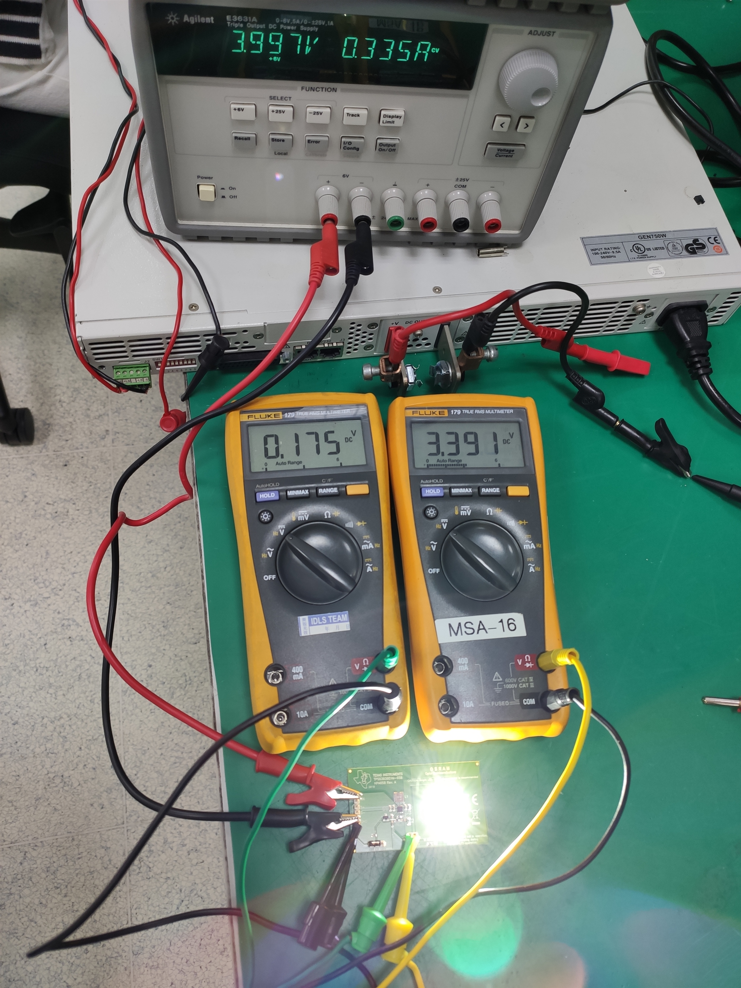
    I did the test based on TPS63030 EVM. The test result matches the user guide well. For example, Vin=4V. Eff=3.39V*(0.175V/0.51Ω)/4V/0.335A=86.8%. 

    I also took a photo to show the setup. As I only has two multi-meter in hand, I just use the measurement result from power source and ignore the voltage drop of cable at input side. (But it doesn't matter for this case, as it only makes the test result a little smaller than real value actually.) 

    For the test you did, I don't think it's caused by bad EVM. It could be caused by cable loss, improper measurement, or unstable. May you do the test with same setup? Better with the original LED.  Thank you! 

    But if you prefer, you can also apply TPS61030 samples from TI.com and replace it in EVM.   

  • I'm not at all surprised by your findings, but do find your conclusions to be unsupported by the data.  Why would I be able to measure a TPS63060 properly and accurately, but not do the same on a TPS63030 (EVM) board?  I use essentially the same setup for both boards, and one performs to spec while the other does not.  Somehow my setup is to blame?  I've also tested an Analog Devices demo board (provided to me at no cost by their excellent customer support group), and their board also performed to specification.  I'm not following how setup is the root cause.  

    As a note, your setup exactly matches mine, except I of course have different equipment.  It's not a difficult measurement to do, and as I said my original testing configuration was tracking battery discharge, so I was collecting via a DAQ.   I don't have the test set-up right now since I am at my office, and I was doing the testing at my home for social distancing purposes.  Regardless, a photo isn't really going to help much.   

    As far as replacing the TPS63030,  I'm not interested in paying to purchase parts (or spending my own time) to repair your board.  The QFN package TPS63030 would not be an easy swap anyway given my available equipment, so there is a reasonable likelihood of damaging the board. I'm also not convinced it's necessarily the TPS63030 anyway.  I was actually considering the inductor as a a possible culprit but didn't think it was in my best interests to waste time shotgunning the board when I could hopefully get a replacement.  That logic was flawed, however, since it seems TI doesn't stand behind their products.  

    I would request a sample as suggested, but TI in their infinite wisdom has decided I am not worthy of being in the sample program when I requested $0.55 in parts for a low-cost ventilator I was working on.   I'll admit I hadn't used the program for about 3 years, as I was just getting parts from distribution as needed (my client had pretty deep pockets and I usually only request samples for customers who are start-ups or from academia).   But when I reapplied during the pandemic (working on that low-cost ventilator), I was rejected.  No reason was given; I did ask and was told that they could not tell me why.  This, despite the fact my last design used (I believe) 22 unique TI parts across 3 internal boards and is going into production with a very large medical device conglomerate.   


  • Hi Jon:

    So sorry for your uncomfortable experience during sample request and other things. As I'm in R&D unit, I'm not familiar with the exact rules of sample team. But I highly suspect they didn't realize what you are working for, and how important the project is. May you check if you can contact the local TI filed team or distribution to find the support. In the same time, I will contact you via private message, to check if I can do more help. 

    Back to the technical issue, we have standard test procedure for all device and EVM. There is very low probability it's failed before you do test.  (I haven't met it after testing nearly one thousand boards.)  Since the circuit can still regulate the output current around 350mA, it doesn't look like damaged.

    But it may be unstable with the equipment or different type load in series, which can escape the observation using multi meters. May you catch the waveform measure the Vin, Vout,L1,L2 to check if it's operating stable in your side? It's also a way to check if the IC operates well. Thank you!

    Hope you are doing well and stay safe!


  • Hi Minqiu.

    Problem has been confirmed, and it definitely is the board.     

    Swapping the EVMs on-board Coilcraft inductor L1 with a Murata 1227AS-H-1R5N=P2 (that I pulled from one of my working TPS63060 boards) corrects the problem.  At 4V input, the current draw went from 485mA to about 340mA, which is pretty much dead-on what you had in the picture above.  That new value corresponds to an efficiency just under 90%.  It's apparent that losses in the inductor on the EVM were the cause of the issue, as I had supposed a few posts back.  I won't presume to guess whether root the cause was manufactuing at TI or component at Coilcraft.  

    Ultimately I still have the same problem, since I do need to move the inductor back to my board.  Guess I'll need to order an inductor to repair the TI board as well if I ever plan to use it again.       

    Let me know if you need any additional details.