Tool/software: Инструменты дизайна WEBENCH®
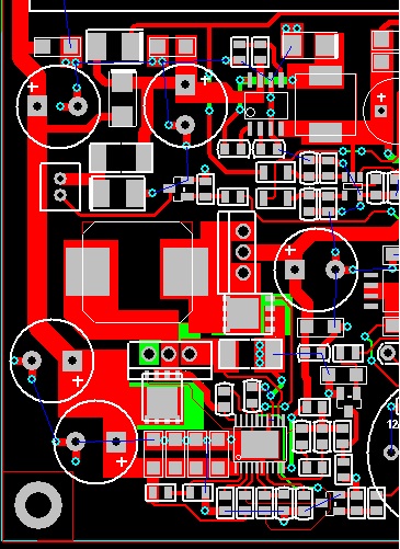
Good afternoon. I make an uninterruptible power supply for a system installed in railway transport. I decided to use the LM5118 chip as a charge controller. An ideal diode controller LM74700 is used as an output diode, ACS712-05 is used as a current sensor. The charge voltage is controlled by the IRLML6346 transistor, which shunts the 1KOM resistor. Management is via PWM from the microcontroller. The main problem is the large current consumption, or rather, the feeling is that for some short period the LM5118 controller which triggers the protection of the DC-DC converter TEP 75-7215WI. For example, I charge a battery with a current of 500 milliamps and a voltage of 28.8 volts. Moreover, the input voltage at Lm5118 is 24 volts. DC-DC converter goes into protection. Or it starts to work in some kind of resonance. I tried to exclude the DC-DC converter from the circuit and connected the LM5118 directly to the laboratory power supply. The power supply starts to ring, the current consumption is also high. I tried to put a choke, a choke and a capacitor between the DC-DC converter and the charge controller. Tried to manipulate the working frequency and ramp of the LM5118. Always one result. The circuit makes a loud ringing. And she has a peak large current consumption. I am attaching to the question the input voltage waveform on the LM5118, the design of the printed circuit board and the printed circuit board itself, perhaps I was mistaken with the wiring. I made the circuit diagram and face values of the radio components according to the proposed TI designer on the site. Which way should I dig, is it a calculation error, or an error in the PCB layout? I would also like to say that such miracles happen only with the battery. The load in the form of a lamp or resistor works correctly, there is no ringing or increased current consumption LM5118. With a resistive load, the circuit works perfectly !!! Where does such self-excitation come from when working on a battery?