This thread has been locked.

If you have a related question, please click the "Ask a related question" button in the top right corner. The newly created question will be automatically linked to this question.

WEBENCH® Tools/LM5022: Webench Design says IC or FET may cross junction temperature- Should I use this design?

Part Number: LM5022

Tool/software: WEBENCH® Design Tools

Hello,

I would like to use LM5022 controller for my Boost converter circuit. I tried to Simulate and check the design in WEBENCH tool.

Below were my inputs for design:

Input voltage range: 16-32V

Output Voltage: 100V

Output Continuous current: 2A

Ambient temperature: 45deg

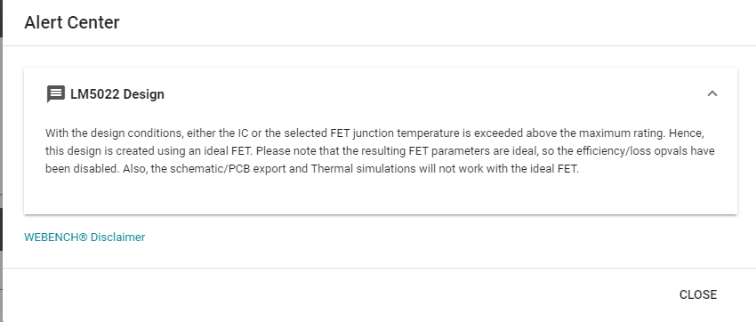
After this, when I check for design, It takes me to design page with message as shown in below image.

Shall I use this IC for my design or not? As per my understanding the Temperature of MOSFET are independent of controller IC. Only concern here is IC itself as it is going to Drive MOSFETs, The current consumption might be the concern here. 

Please help me understanding the message here and guide me for usage of the LM5022.

Regards,

Ankit

  • Hi Ankit,

    Unfortunately, the image did not show up in your post. Can you re-post the message? 

    Thanks,

    Richard

  • Hello Richard,

    Copying the message here:

    With the design conditions, either the IC or the selected FET junction temperature is exceeded above the maximum rating. Hence, this design is created using an ideal FET. Please note that the resulting FET parameters are ideal, so the efficiency/loss opvals have been disabled. Also, the schematic/PCB export and Thermal simulations will not work with the ideal FET.

    Image file is also attached.

    Regards,

    Ankit

  • Hi Ankit,

    In Webench, the thermal simulations assume natural convection and no airflow, and utilizes Theta_ja in calculations. Therefore, the situation that Webench shows you will not take into account your actions to reduce junction temperature increase in the FET and IC.

    The current consumption of the VCC regulator in the IC is equal to Ivcc + Qg*Fsw, and power dissipation in the FET is the sum of its conduction and switching losses.

    That being said, what you can do in your design with the LM5022 is to mitigate thermals through your layout and part selection, and you will need to test the design to observe thermal behavior. 

    Thanks,

    Richard