This thread has been locked.

If you have a related question, please click the "Ask a related question" button in the top right corner. The newly created question will be automatically linked to this question.

UCC256302: Soft-Start and Burst-Mode

Part Number: UCC256302
Other Parts Discussed in Thread: UCC25630-1EVM-291, UCC25600

Hi,

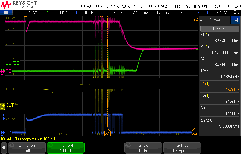
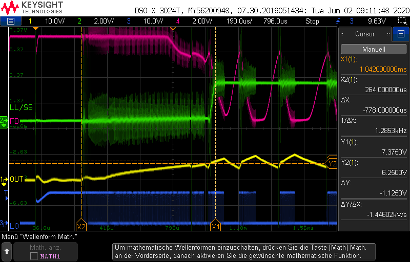
during Soft-Start I get the following waveforms:

No-Load:

Full-Load:

Questions about SS at full-load:

1- why is the switching interrupted during SS?

2- why does SS end before FB<SS?

Questions about SS at no-load:

1- why does switching stop so early and even before SS is finished?

2- why does SS end before FB<SS?

Other than that I have problems with burst mode:

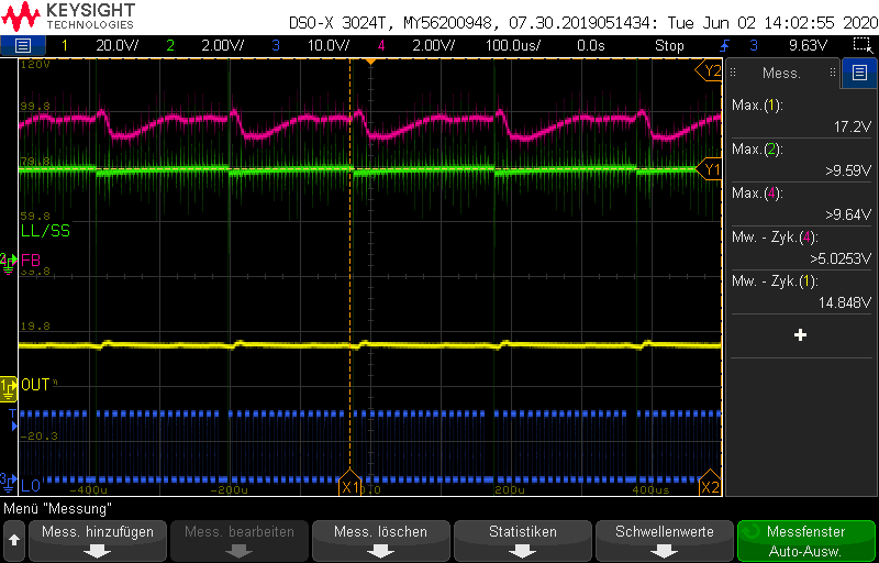
I removed the upper resistor at LL/SS pin to reduce burst mode threshold. But this doesn't work. Burst mode stays active even with full load! The figure below shows this state:

burst mode at full load:

After every 15 pulses, a very small burst off period is produced.

Tanks in advance.

Best regards,

Ehsan

  • Hello Ehsan,

    Is it possible for you to provide the converter schematic diagram and details about the input and output design targets and the test conditions during the waveforms shown above, please?

    Regards,

    Ulrich

  • Hello Ulrich,


    Thanks for your prompt respond.


    The complete circuitry can unfortunately not be published. Although, I can give you a description of the system.


    The input is a 550 V DC-source and the output is to be controlled at a constant 15 V for a range of 0.1 to 50 W. I based the design on UCC25630-1EVM-291 from TI and used Excel Design Tool REV. B for the most part. Below are a number of components on our board (the numberings correspond to the ones on the evaluation board):


    R14=removed
    C17=100n
    C9=470p
    C10=30n
    C7,8=22n
    L1=140u
    R23=5K6
    R20=12K
    C28=47n
    Mutual Ind.=2mH
    Turns Ratio=158:9
    Opto=PC357


    The tests above have been conducted for the mentioned nominal voltage. No load : 0.1 W and full load : 50 W. Further measurements can be conducted upon request.


    I would be thankful, if you could share with us your assumptions based on your experience with the IC.

    Best regards,
    Ehsan Sharifian

  • Hello Ehsan,

    My experience with this controller is actually very minimal, however I will work with others in the background to help solve your problem.

    When you mention that you used the Excel Design Tool "for the most part", I wonder if the part(s) which you did not use may account for the full-load burst-mode operation.  For example, since the EVM is designed for up to 410Vdc maximum bulk rail and for a 120-W power level, your revision to 550Vdc and 50-W max may have overlooked some necessary burst-mode setting change.  In this case, an EVM-level setting could be allowing burst operation at full load. The start-up issues may be caused by a similar oversight.

    It would be helpful to obtain the LLC portion of the schematic diagram and a copy of your Excel Tool as you used it. To remain private, you may email the files to me at ulrich_goerke@ti.com. They will be kept strictly confidential.  Having all of the actual components, values, and connections visible will eliminate guess work and assumptions on our part for circuit details that are not mentioned in your previous post.  Debug advice based on bad assumptions is unproductive.

    Regards,

    Ulrich

  • Hello Ehsan,

    Here is some additional information from my colleague:
    " The converter is not stable. The FB pin voltage is moving up and down which would indicate the FB pin current (the actual FB signal) is moving all over the place as well. The controller stops switching when the FB signal is less than the burst threshold.

    The soft start ended early because the feedback network demanded a lot of current out of the FB pin prematurely and pulled FBreplica to be lower than the soft start pin voltage. Note: the actual FB signal is the FB pin current, not the FB pin voltage. The decision to exit soft start is made when the internal FBreplica becomes lower than the burst threshold."

    Based on this advice, I recommend that you investigate the loop compensation at the secondary-side shunt regulator and adjust it for stability.
    My previous advice is also still valid.

    Regards,
    Ulrich

  • Good day Ulrich,

    Thanks for your reply and apologies for my delayed answer.

    EVM has been used only as an example. The whole system except for the feedback has been designed according to the design tool.

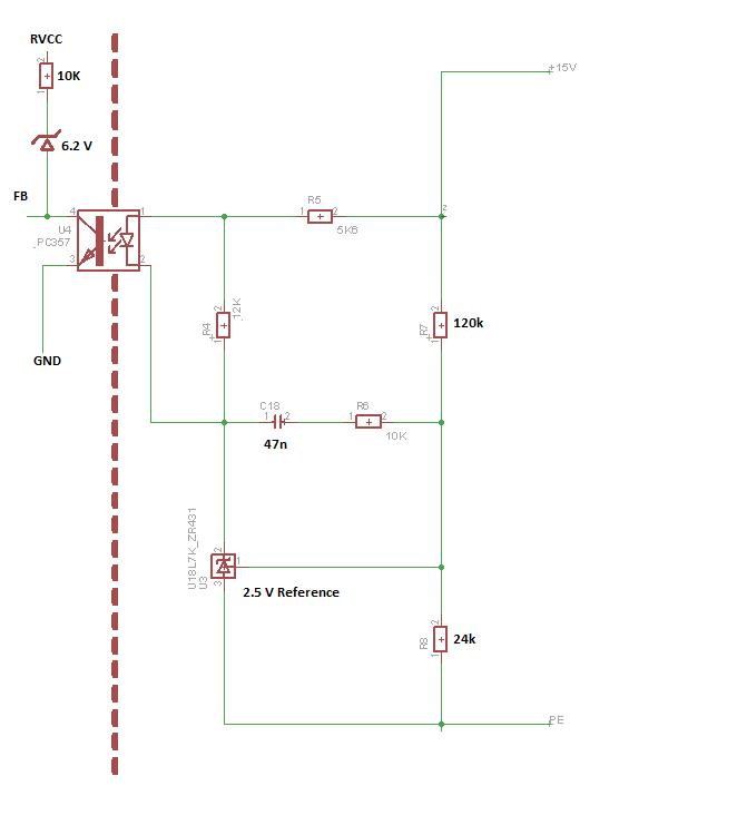
    The feedback seems to be too sensitive and moves around to much. Here is the feedback circuit:

    How could the feedbadck be adjusted for less reaction?

    Could the fault be resulted from a big Ln=14 and that the controlability is too small? (I already doubt it, because the example in the datasheet specifies this value to be around 13, although common practice is around 4 to 6 or 7)

    Best regards,

    Ehsan

  • Hello Ehsan,

    Try following the design feedback design procedure in this reference for the UCC25600 LLC controller: https://www.ti.com/lit/pdf/slua582 .

    There are a number of other useful technical papers to review under the UCC25600 product folder.  I wish there were links to these from the UCC25630x folders. 

    Regards,
    Ulrich