Other Parts Discussed in Thread: BQ51013
I’m working on a new design using the BQ51013B wireless charger. I’m having trouble getting the output current over 400mA. I’ve included scope shots of no load, 150mA and 400mA. Up to 150mA the rectifier voltage stays above 5V during communication, however between 150mA and 400mA the rectifier voltage sags below 5V during communication and drops below the UVLO above 400mA. Looking at page 11 of the datasheet I can see that the output current should be limited during communication but it doesn’t look like the rectifier voltage drops.
I followed the procedure on pages 29 and 30 to measure the inductance of the coil and calculate values for C8 and C10. I then adjusted the value of C10 to get the best connection to the TX. I also lowered R_ILIM but that didn’t help much.
Schematic

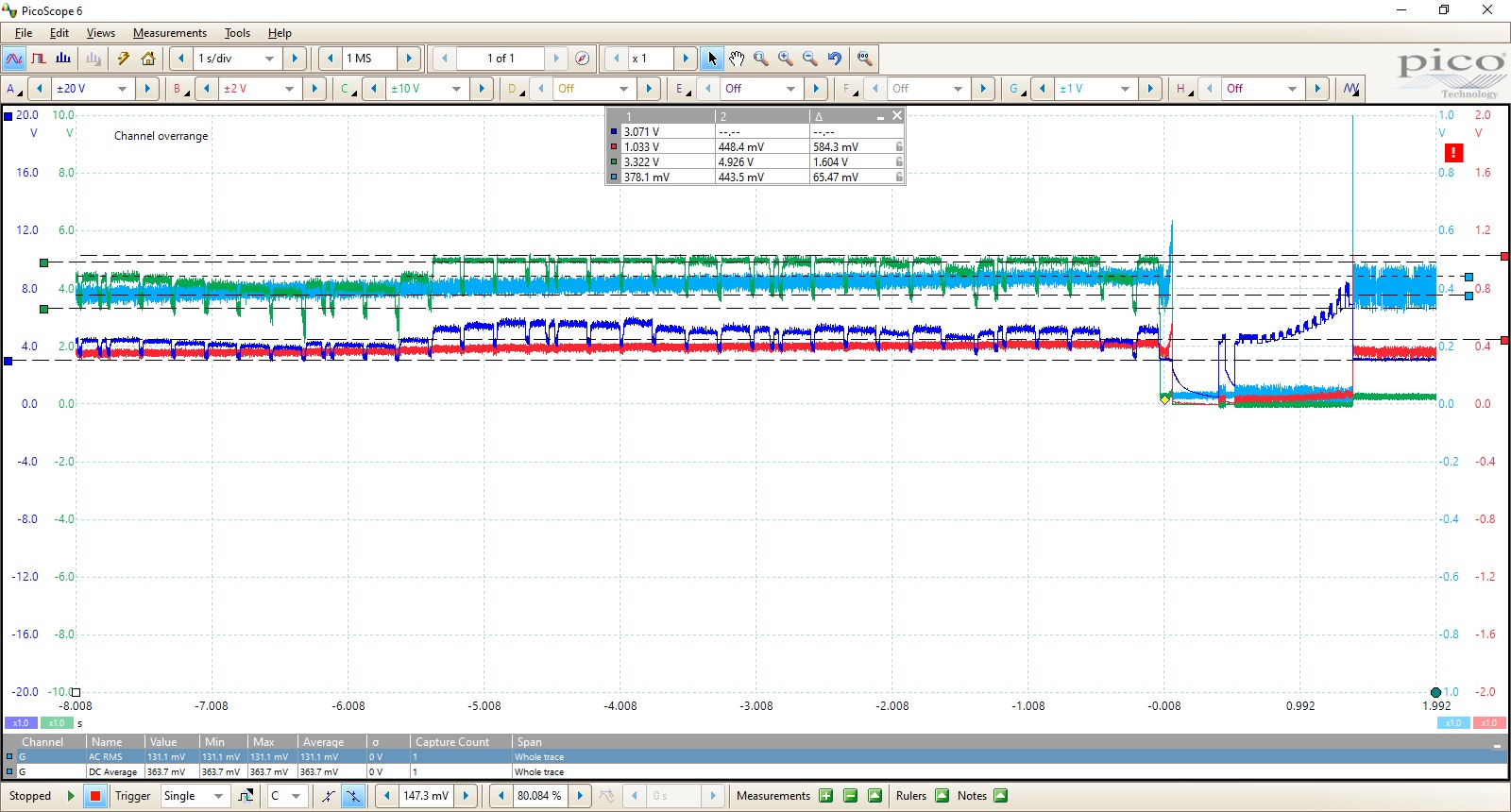
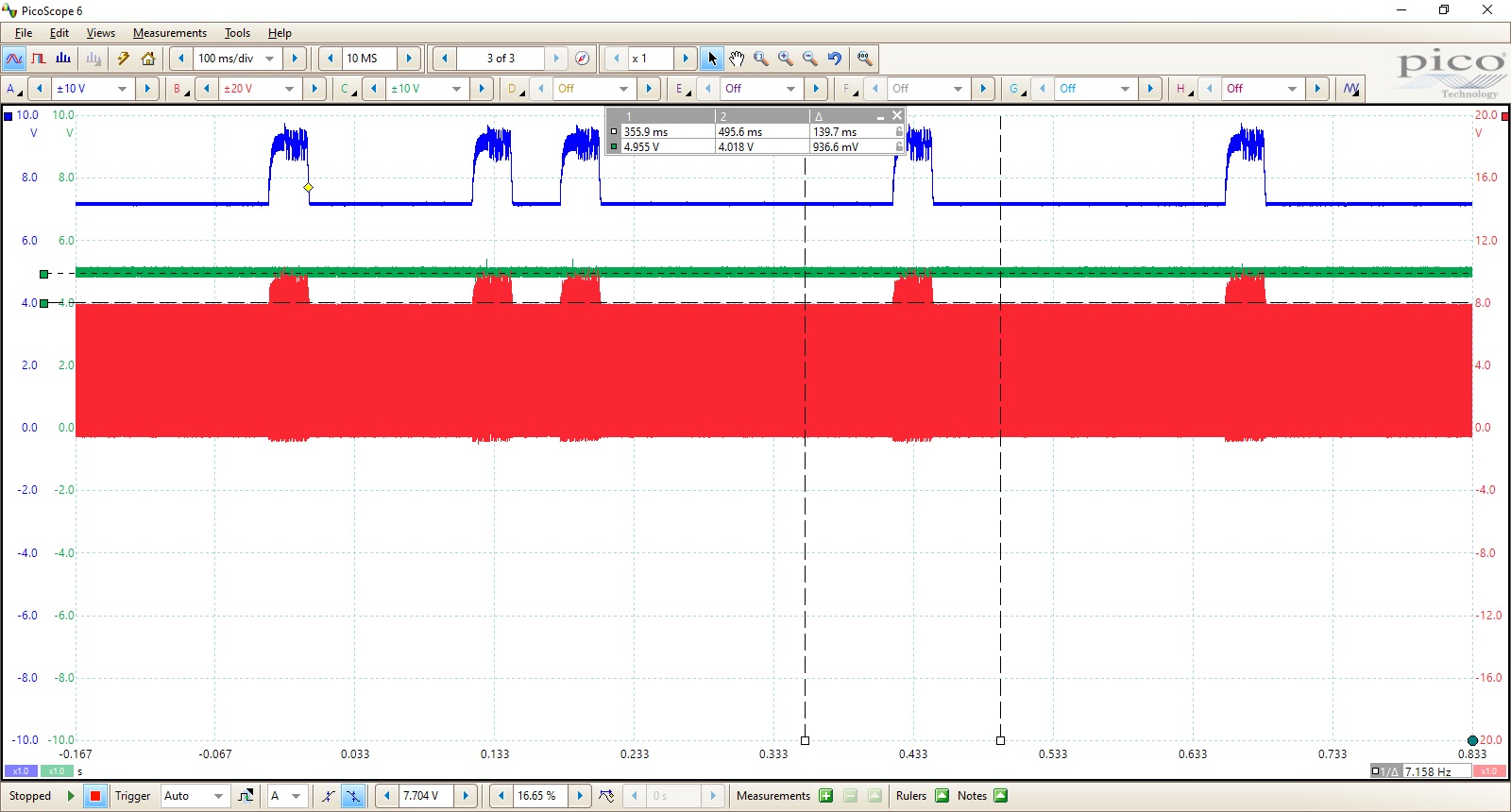
No Load (Blue = RECT, Green = OUT, Red = COMM1)
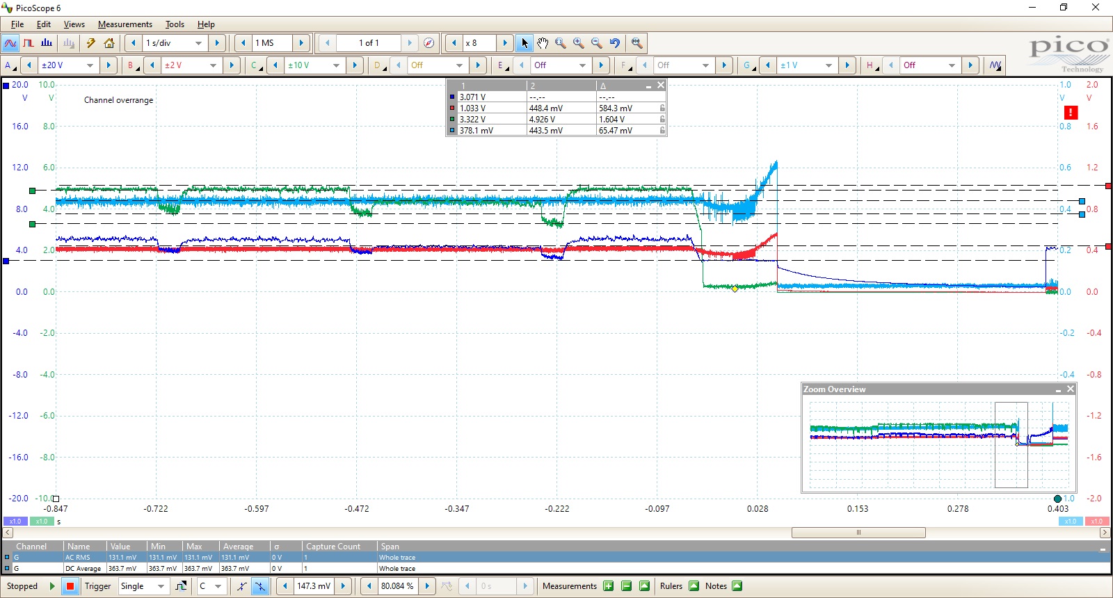
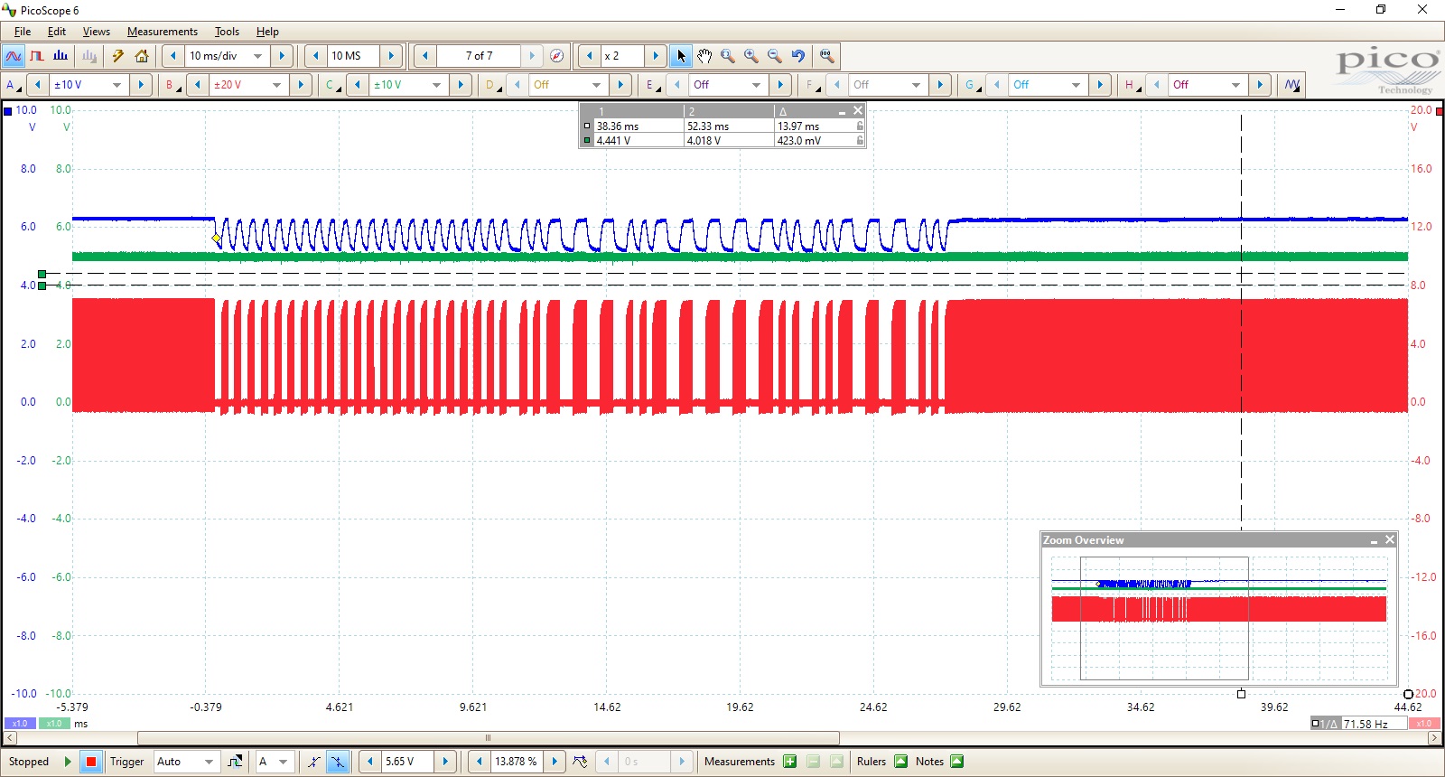
150mA
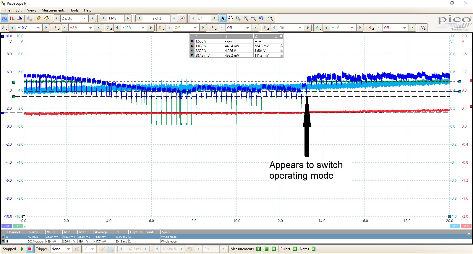
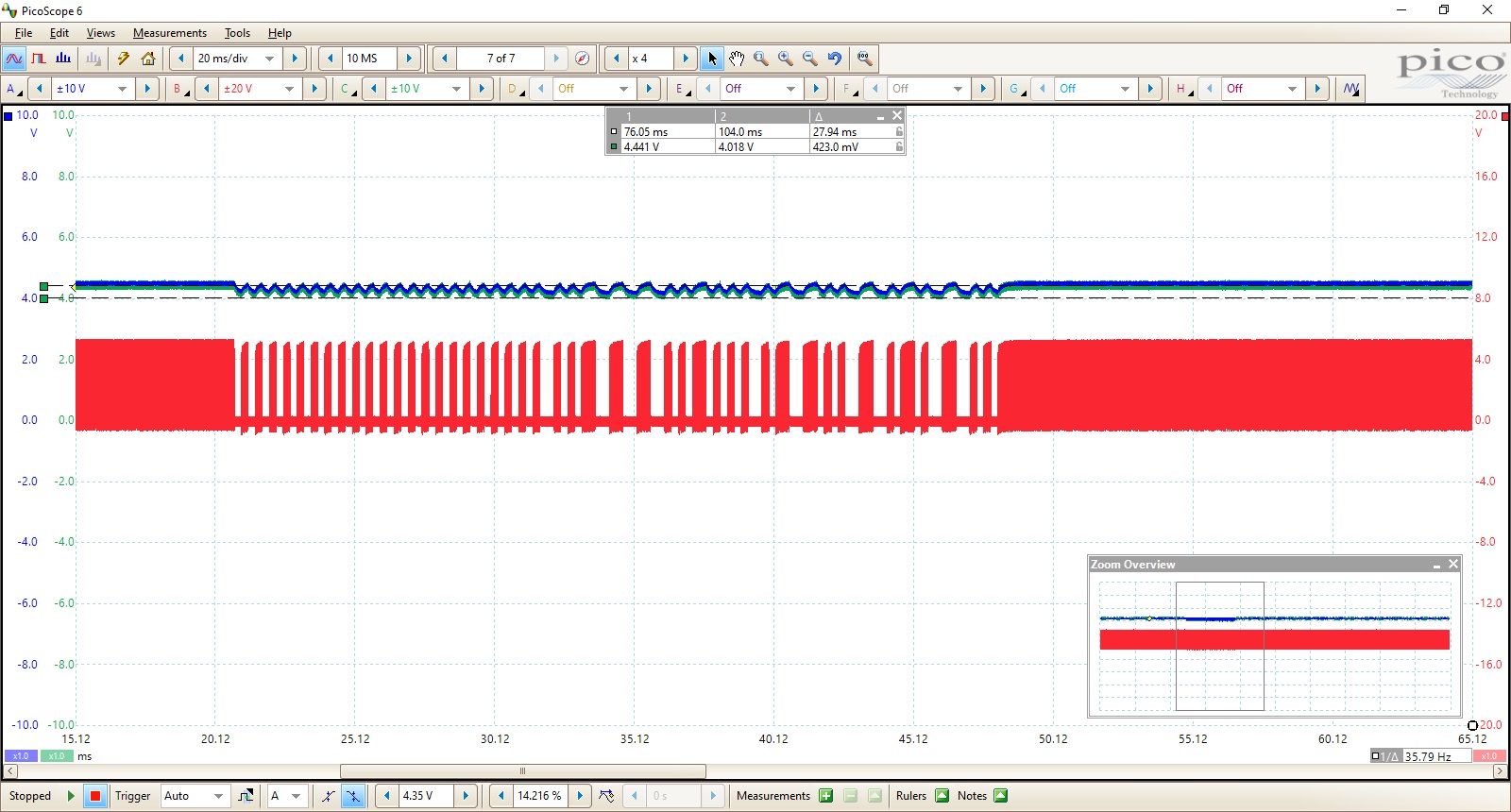
400mA
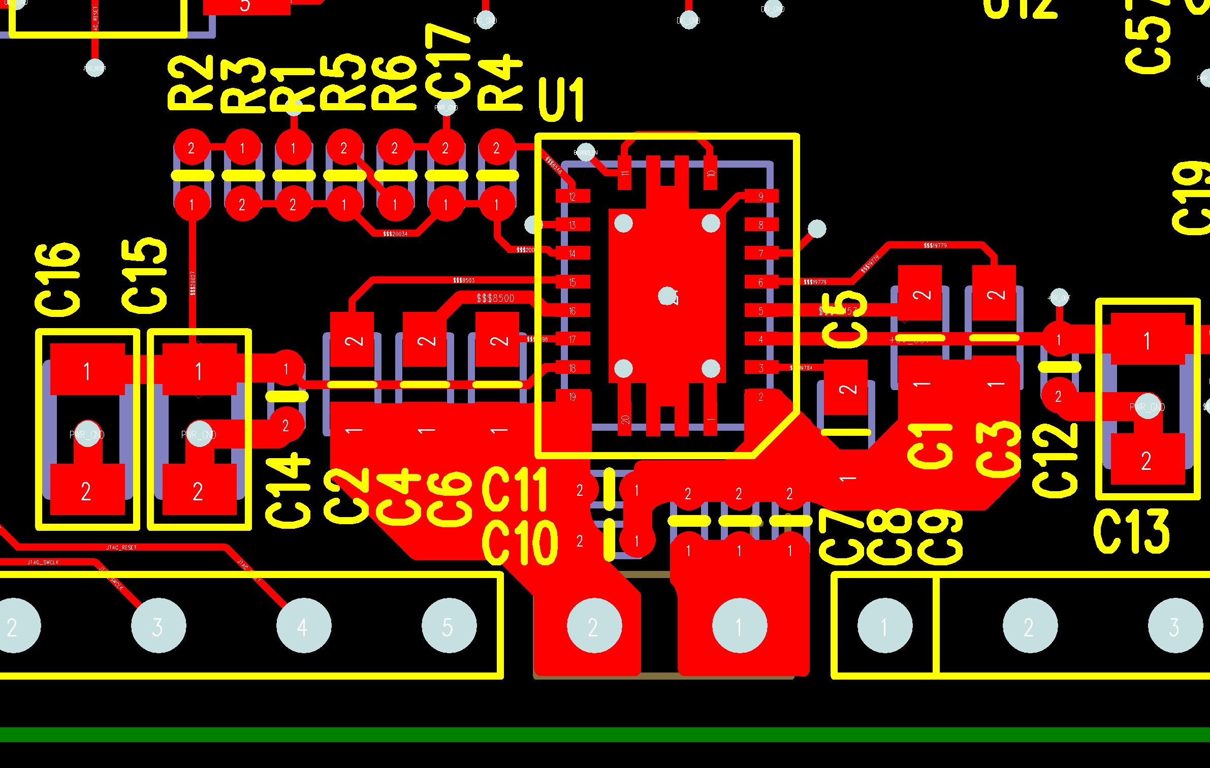
Layout