Other Parts Discussed in Thread: BQSTUDIO, BQ34Z100, EV2400
Hi,
in order to create a Golden Image file I've used the BQStudio Software and the BQ34Z100-G1 EVM board. It worked well.
Now we implemented the BQ34Z100-G1 into our PCB. Communication via I²C is working great.
My question is about the content of the Golden Image File and the checksum. Here just one small part of it:
;Unseal device
;--------------------------------------------------------
W: AA 00 14 04
W: AA 00 72 36
W: AA 00 FF FF
W: AA 00 FF FF
X: 1000
;--------------------------------------------------------
;Go To ROM Mode
;--------------------------------------------------------
W: AA 00 00 0F
X: 1000
;--------------------------------------------------------
;Data Block
;--------------------------------------------------------
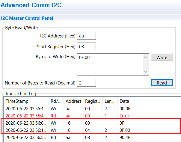
W: 16 00 03 00 00
W: 16 64 03 00
X: 20
C: 16 66 00
W: 16 00 02 00 00 00 EA FF 33 B1
1)
The beginning makes sense with "W: AA 00 14 04"
AA is the adress, 00 the register and the 14 04 the unseal key and so on.
But starting with the Data Block the W: 16 00 03 00 00 or W: 16 64 03 00. Why the address is changing to 0x16? There is no information about it in the datasheet of the BQ.
And what register is 0x64? also no information in all sheets of the BQ34Z100-G1. Normally I know TI that they do great datasheets, but this time.... -,-
2)
At the end of all data block writings there should be done a CheckSum calculation. Is this calculation already inside the Golden Image file at the end? Or should I do it by my own after every 32 Bytes?
Thank you
Regards
Markus