This thread has been locked.

If you have a related question, please click the "Ask a related question" button in the top right corner. The newly created question will be automatically linked to this question.

WEBENCH® Tools/LM3409HV: LM3409HV FET Dimming effect

Part Number: LM3409HV
Other Parts Discussed in Thread: LM3409

Tool/software: WEBENCH® Design Tools

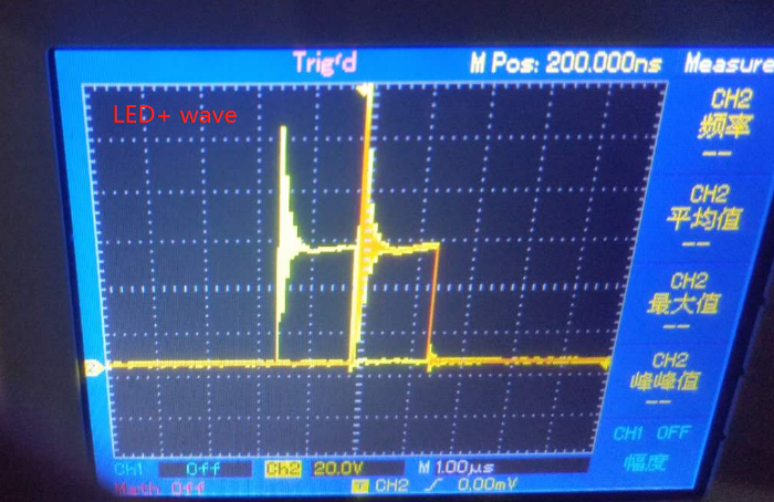
hello ,I recently tried LM3409 FET dimming again,It was found that the change in lamp brightness did not match the input PWM duty cycle, and there was a sudden change in brightness.

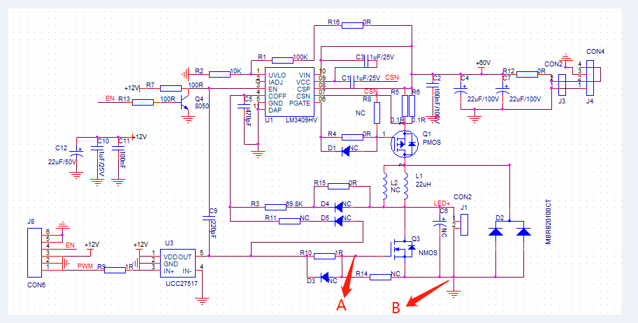
I first check the input PWM waveform,It is found that the load will affect the FET MOS waveform. Is this the reason why the lamp dimming is not soft enough?Is there any way to solve?

  • Hello,

    What type of PWM dimming are you doing?  Shunt FET dimming or Enable dimming?

    What is your load?

    I suspect the 'noise' is being picked up the the scope probe.  One picture is without current, the other is with current.

    Are you watching the input voltage when you are dimming?

    This is a hysteretic controller so it should dim well.

    What is Vin, what is the output voltage?

    Best Regards,

  • hrllo,i used Shunt FET dimming.Input is 60V.and it is keep 60v also.  output is 54V/4A.how to clear the“noise”?

    thanks very much.

  • Hello,

    This is a switching LED driver, there will be noise.  How are you connecting your scope probe to the circuit?  Is you LED load close to the output?  Where is the shunt FET located?  Do you have an output capacitor?

    What is happening when you are dimming.  Does the PWM follow the drain of the Shunt FET?  Can you observe the LED current?

    Best Regards,

  • hello,I test point A and B.

    My input PWM duty cycle is 0->27%->0 cycles, the duty cycle changes the same unit every time (25MS changes once, each change is about 7nS pulse width). It was found that there were areas of bright and dark during the change of the brightness of the lamp bead, so I checked the NMOS waveform and found that there is noise with and without LED. I don’t know if this noise caused the brightness of the lamp bead to change softly.

  • Hello,

    "How are you connecting your scope probe to the circuit?"  I mean how are you attaching the oscilloscope ground and probe tip to the circuit?  I don't believe the ringing you are observing is causing a light output issue.

    Can you observe the LED current during operation?  You need to be able to see the inductor current when it is shunted and when it it providing current to the LED.  Current represents light output, if it changing the current is probably changing.

    Best Regards,

  • Hello, I lead a small wire at the negative end of the lamp bead, and then the oscilloscope probe directly measures the NMOS G pole. I don't have an instrument that can measure the current waveform. If the noise does not affect the brightness of the lamp beads and there is a sudden change, where can I start to analyze the problem. The mutation occurs only in a small area during the entire dimming process.
    Thank you very much.

  • Hello,

    If you cannot measure current watch the output voltage and see if the duty cycle and amplitude stay constant.

    Do you have a probe ground you are using or are you using a small loop connection to the gate?

    You can also look at the voltage across the current sense resistor.  You cannot use the scope probe ground clip, you will need a low inductance connection to measure without noise pickup.  The loop created by the probe ground will allow too much noise in the measurement.

    Best Regards,

  • hello.There are many oscillating waves at the beginning of the lamp when there are waveforms at both ends of the lamp bead (the LED positive picture on the first floor). This situation does not occur if you use EN dimming. When measuring with an oscilloscope, I measure in the same way. Obvious shock waves can be found with and without lights.
    Because I don't have this LM3409 DEMO board, can you use the DEMO board to measure the standard waveforms of the NMOS G pole and the LED+ wave?and  show me the measurement picture.
    Thank you very much.

  • Hello,

    EN dimming turns the gate off and on, the inductor limits the slew rate of the current so it will be much less "noisy".  Shunt FET dimming is shunting the LED current through the shunt MOSFET, the transition is fast and will cause high di/dt which will be pickup up in a scope loop.  I recommended looking at other waveforms and have not seen results.  If the light is changing the current, most likely, is changing.  If the output current is correct then the duty cycle may be changing, this can be see by the voltage across the LEDs.

    Best Regards,