This thread has been locked.

If you have a related question, please click the "Ask a related question" button in the top right corner. The newly created question will be automatically linked to this question.

TPS63002: Typical Application schematic from datasheet not working

Part Number: TPS63002

Hi,

I wanted to use the TPS63002 to output a reliable 5V from a noisy 5V source. I just used the typical application schematic recommended in the first page of the datasheet but for a 5V output

However, my boards with this circuit are acting like there is a short between power and ground and are maxing out whatever current limit I impose from the power supply. I've isolated it to this circuit through disconnecting things upstream (No current draw at all) and downstream of it (Back to max current draw). It doesn't seem to be a fab issue since it's affecting all boards and my continuity tests show all pins hooked up as intended with no unexpected shorts.

I think it must be an issue with my design. Does anyone see something I'm doing that's obviously wrong? I've triple checked the pin numbering and it seems okay. Any help would be greatly appreciated.

TPS63002DRCT

  • It seems like my schematic in the original post didn't make it in, let me try again:

  • Hi Colin,

    did you measure the impedance between the GND pin and other pins? make sure the IC is not damaged.

  • Hi Jasper,

    Impedance measurements seem okay to me. With respect to GND:

    1 (VOUT)  550k

    2 (L2) 800k

    3 (PGND) 0.2

    4 (L1) 800k

    5 (VIN) 650k

    6 (EN) 650k

    7 (PS/SYNC) 650k

    8 (VINA) 650k

    9 (GND) 0.2

    10 (FB) 500k

    And the IC doesn't seem to be damaged upon visual inspection. This has been consistent on each of the boards I've tested, and they're coming from a fab I trust.

  • Hi Colin,

    could you help to measure the VIN, inductor current and VOUT waveform when observation the issue. the inductor current can be measured through place a line in series with the inductor.

  • Hi Jasper,

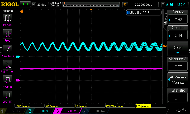
    So I measured the VIN and VOUT waveforms and saw this oscillatory behaviour on the input (Turqouise).

    And then when I wanted to measure the inductor current, I added a 10 ohm inline resistor for measuring. And it seems to be working perfectly with that in place. So it seems like the problem came down to my inductor selection.

    Does anyone see any redflags with this part?

    Mfr: Murata

    Mfr Part #: 1285AS-H-2R2M=P2

    Thank you for the suggestion to check the inductor current!

  • Hi Colin,

    the inductor is OK. and you can't add 10ohm in series with inductor.

    but the input voltage is not correct. please change to a power supply with stable input voltage.

  • I realize there isn't supposed to be a resistor in the inductor path, I just placed one there on your recommendation for measuring the current. I just found it interesting and confusing that it makes the circuit work.

    The input voltage is low because something is maxing out current draw from the benchtop supply, it's acting like a short. I think the oscillation is because I have a TBU upstream (surge supressor device) which is turning on and off as the current goes beyond it's limit of 500mA. But I've tried skipping the TBU and connecting my benchtop power supply directly to VIN and still had the same issue. Even with the current limit increased to 1.5A it still just maxes out unless I add impedance to the inductor path.

  • Hi Colin

    it is strange, could you share your layout? also please apply an EVM for reference. 

  • What is an EVM?

  •  I didn't see risk leading to this issue from the layout. the EVM is the evaluation board https://www.ti.com/tool/TPS63000EVM-148

    please apply an EVM for reference

  • Okay, I've done some more testing and I'm still thoroughly confused. 

    I didn't have an evaluation board handy but I remembered I had used this on a different board a few years ago with no problem. After looking at it I realized I had basically copy and pasted the design over. Identical part choice, very similar layout. I fired up the old boards and they are working just fine.

    So I wondered if things downstream from the TPS63002 were a problem. So I hooked up the 5V output from my old working board to this new problem design, feeding what 5V would go into (and disconnecting the TPS63002 on the new board) and it worked just fine.

    Then I though maybe the surge protection stuff upstream of the TPS63002 was the problem. So I input the voltage to my new board. Brough the output the surge protection to the input voltage of the old board. And then brought the output of that to the new faulty board. And it worked just fine.

    So then as I thought maybe I got unlucky with this batch of TPS63002. So I moved the old one from the working board and replaced the one on my new design and tried it out. SAME ISSUE. And it's still fixed by adding 10 ohms to the inductor path. So at this point, it seems like the only thing that could be wrong in the new design is the layout. But based on my measurements, and staring side by side at the two layouts I really don't see anything wrong.

  • Hi Colin,

    that is strange, but it is not impossible.

    1.  try change all the external components related to the buck-boost in the new boards. avoid some components are wrong.

    2. check if the PCB is correctly build. every track, vias and connection. I met such issue below, a via is not correctly built.

  • Okay following up on the last post. I mentioned that I tried transferring the IC from an older board to the new board and it DIDNT work. Today, I tried it and it actually DID work. So I tried transferring another old IC to a new board and at first it didn't work. But then after a minute or so it did. I think I was too impatient and I guess the chip was still too hot from reflow.

    So it seems like swapping the IC is making things work. As I mentioned before I tried the adjustable version and still had problems, but I'm going to try ordering the part that's supposed to be on there to make sure the CM didn't get the wrong part on it. Or to see if it was that specific batch of ICs that were a problem. Updates to follow!

  • Hello Colin,

    Thank you very much for the update.

  • Trying out some other new ICs gives me the same issues as always. It seems like the only situation that I've found to work is using a TPS63002 chip bought in 2017.

  • Okay phew, I think I finally have this solved. It was something I had checked out at the beginning of my debugging process but circled back to it and it seems to be working well.

    Basically the issue seems to be surge suppressors upstream of the device limited the high startup current necessary to have the TPS63002 work. I'm wondering if earlier revisions of this part had a lower startup current which is why I was seeing chips from other devices working when I swapped ICs (That also explains the temperature needing to cool immediately after starting it).

    I had earlier tried taking off all parts upstream of it and tested it and it seemed to have no effect. So I'm wondering now if I had left some other modification I had made while debugging and wrongly come to the conclusion that the surge suppressors were not the culprits. Either way, I happened to try it this time and things work as expected. I have now tried it on 5 different boards varying the load from minimum to maximum expected and so far so good!

  • Hi Colin,

    I closed the post as the issue is solved. thanks.