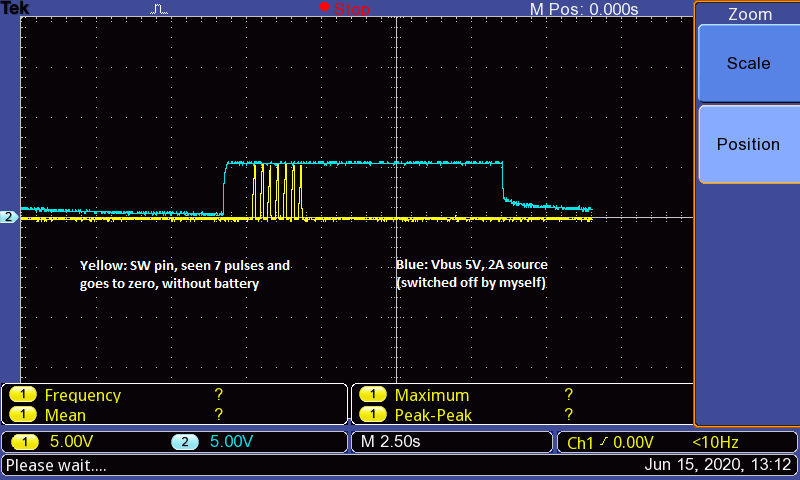
This thread has been locked.

If you have a related question, please click the "Ask a related question" button in the top right corner. The newly created question will be automatically linked to this question.

BQ25886: BQ25886 not working

Part Number: BQ25886

Hi,

I am using BQ25886 in standalone mode and not using OTG feature. I have some questions and issues with it, kindly suggest with the solutions, 

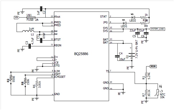
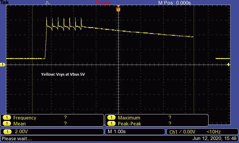
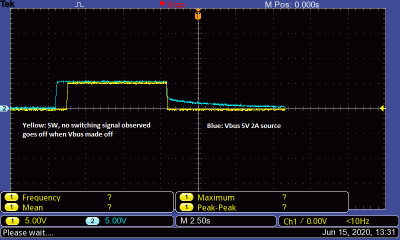
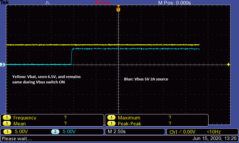
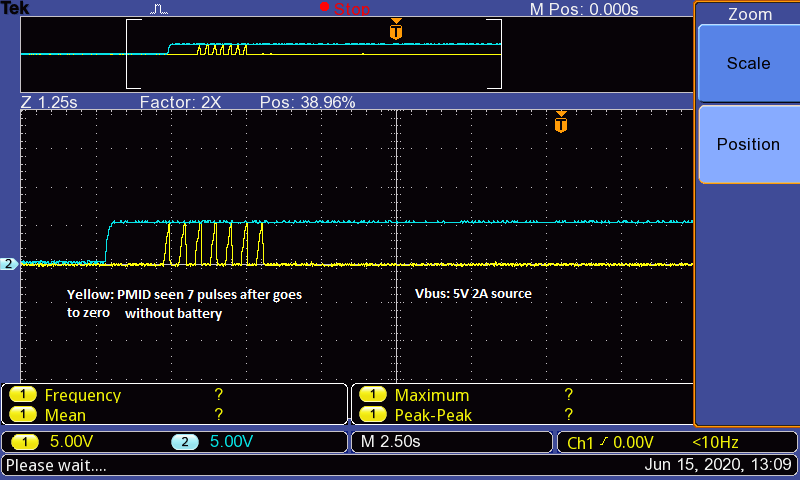
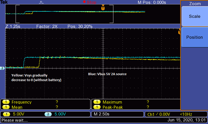
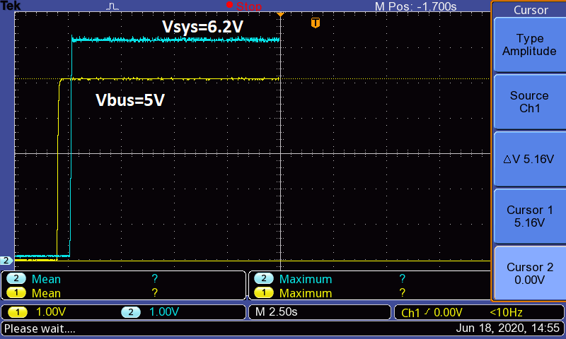
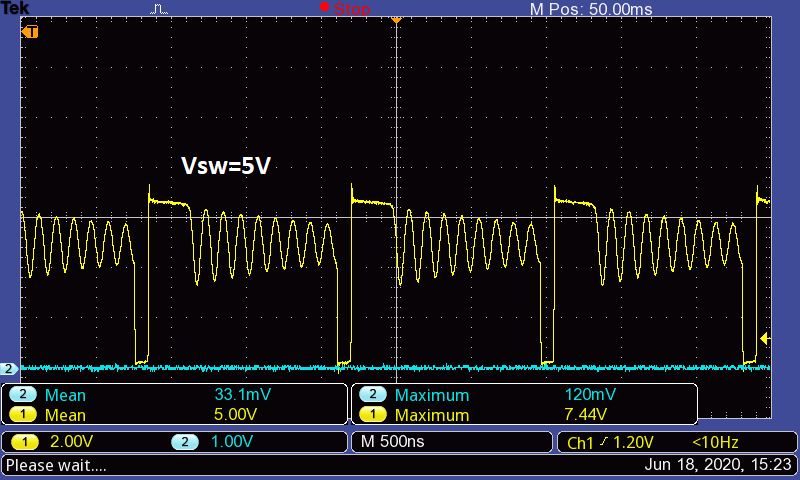
1)  If i do not connect battery, I am not getting any voltage across SYS pin with input supply of 5V, 2 amp source,

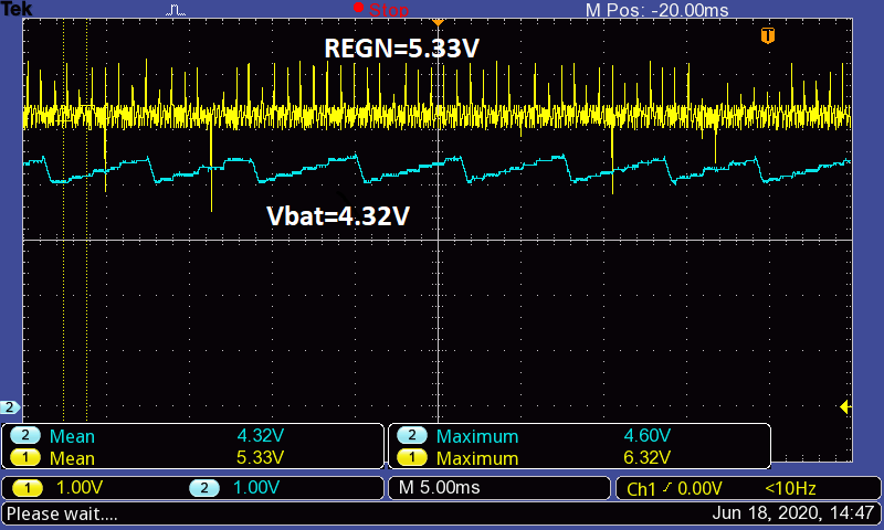
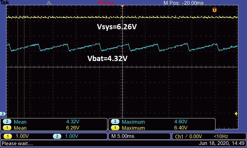
2) I have set Vset to 8.4V (Rset=150k), But voltage at BAT remains same with battery voltage 6.5V. Also the STAT LED is ON.

3) Since I am not using USB OTG, I have shorted D+ and D- with 200 ohms resistor (not updated in schematic). and OTG is connected to ground. 

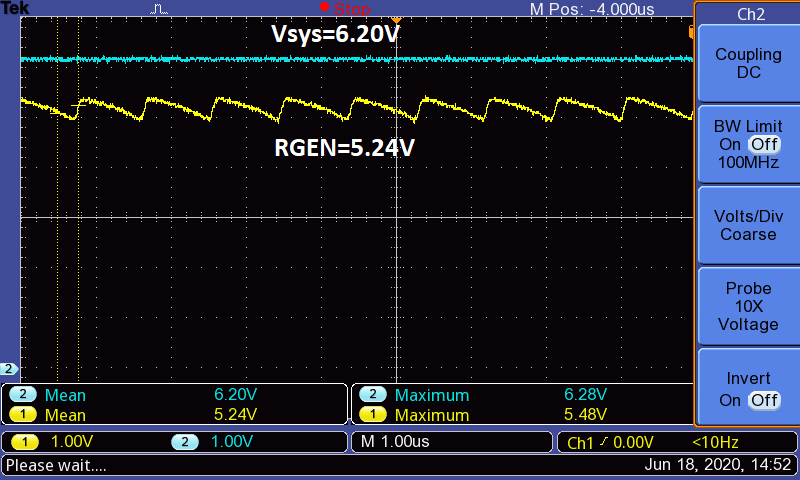
4) ILIM is set to 2A using 555ohms resistor and Ichgset to 1A using 3.81k. (Also 10uF capacitor is connected to PMID w. r. t ground which is not updated in schematic)

As specified in datasheet, I do hope all connections seems good, but dont know the reason why it is not working. Please reply if any design issue in the circuit.

Please find the circuit ,

  • Dear Vishwanath,

    We recommend 10 uF minimum on PMID. Can you please capture waveforms of VBUS, BAT, SYS, and SW when you are having problems?

    Thanks,

    Mike Emanuel

    Please click "This resolved my issue" button if this post answers your question.

  • Hi Mike Emanuel,

    I will capture and share the waveforms,

    As per my analysis and observation, Vbus is 5.2V, BAT is 6.7V (battery voltage with battery and 0V without battery), SYS=6.7V (with battery connected and 0V without battery), SW is 8.7V (with 0.5V ripple)

    thanks,

    Vishwanath G

  • Hi Michael Emanuel,

    Since We do not have 4 channel DSO, I could not able to take all waveforms as you mentioned. Please go through below waveform of Vsys and Vbus input voltage.

    Input source is 5V 2A source, when connected without battery, 7 pulses can be seen in Vsys and gradually it decreases to 200mV. I will try to give the remaining waveforms 2 at a time, please co-operate.

    Also need answers for the following questions..

    1) I am not using OTG and it is grounded. And D+, D- is shorted with 200ohms resistor, How does it works when ILIM having 555 ohms resistor? Which current selection will be prioritized?

    2) As datasheet specifies, is it entering to HIZ mode? Since STAT LEd blinks 7 times and goes off?

    Please clarify and suggest me to make it work..

    3) I have planned to try by removing 200 ohms at D+ & D- and setting ILIM for 300 mA to 500mA and observe result, Does it works?

    thanks,

    Vishwanath G

  • Hi Michael Emanuel,

    Please find the waveform below,

    thanks,

    Vishwanath G

  • Hi Michael Emanuel,

    please find the attached folder regarding waveforms which you asked,

    thanks,

    Vishwanath GBQ25886 waveform.zip

  • Hi Michael Emanuel,

    please find the attached folder regarding waveforms which you asked,

    thanks,

    Vishwanath G4643.BQ25886 waveform.zip

  • Hi Michael Emanuel,

    please find the attached folder regarding waveforms which you asked,

    thanks,

    Vishwanath G7585.BQ25886 waveform.zip

  • Dear Vishwanath,

    Can you confirm that your are measuring the pin VBUS on the schematic and not that VIN label? In addition, can you measure the impedance from the adapter to the VBUS pin? I am concerned that the voltage at VBUS is different than the VIN label.

    Thanks,

    Mike Emanuel

    Please click "This resolved my issue" button if this post answers your question.

  • Dear Emanuel,

    I am measuring at Vbus only, near decoupling capacitor C2 end (measuring 5.1V). And the impedance from adapter to Vbus is 0.2 ohms, seems very less and negligible voltage drop. 

    The adapter is not having D+ and D- pins, Load testing is done for the adapter up to 2.5 amps, no issues observed.

    PG LED also goes off when adapter is powered ON and STAT LED comes ON during power ON with battery. But voltage shows battery voltage.

    When battery is not connected and powered ON, PG LED glows continuously and STAT LED blinks for 7 times and goes off. Vsys reaches to 5V and gradually decreases to 200mV. Vbat is 0V. 

    Tried by removing 200 ohms between D+ and D- (kept open), no positive result, included 5 ohms resistor for Vsys before 44 uF capacitor, No positive result, ILIM and ICHGSET resistor limited to lower input and charging current respectively, no positive result,

    please suggest what else can be done.

    thanks,

    Vishwanath G

  • Vishwanath,

    Do you have a system load and if so how much?

    Can you please probe the REGN, STAT, and /PG voltages? I need to verify REGN is on.

    Last, did you ever try to add the PMID capacitance? This is necessary for operation of the converter, yet there is no capacitance in your schematic. Please add this and let me know if anything changes.

    Thanks,

    Mike Emanuel

    Please click "This resolved my issue" button if this post answers your question.

  • Dear Mike,

    As in told, in schematic PMID cap is not updated. But I have put 10uF capacitor for PMID. Also tested with 20uF, no positive result. 

    Without battery connected, If I turn on the power, REGN is measuring 0V, means LDO not getting on. /PG LED goes high in this case. Vsys reads 0V. STAT LED blinks 7 times and goes off permanently. 

    With Battery connected and turned on the power, STAT LED turns on continuously, but Vbat is same as battery voltage around 6.5V. Vsys reads same of battery voltage 6.5V.

    I have one more observation, If I remove 4.7uF REGN capacitor, (without battery),  REGN=5V,  Vsys=6.2V, /PG LED: ON, STAT LED: OFF.

    If i connect the battery to the above configuration, Vbat is same as battery voltage i, e, 6.5V.

    Please suggest further,

    thanks,

  • Dear Vishwanath,

    Just to be clear, the PMID capacitor is not optional. The fact that REGN is not turning on is indicating a problem with your input source. Can you please verify that your input source is valid? Has the fuse been blown?

    Thanks,

    Mike Emanuel

    Please click "This resolved my issue" button if this post answers your question.

  • Hi Mike,

    I am confirming 20uF capacitor on PMID pin is included.

    How can we get REGN=5V when recommended 4.7uF capacitor is removed from it if fuse is blown?

    In this situation we are getting Vsys=6.2V. and Vbat=4.4V without battery, if we connect battery then Vbat stays at battery voltage only. 

    We verified and validated our input source is 5V 2A to its range, which is our customized design, which does not has D+ and D-, Is this lead to kind of a problem?

    thanks

  • Dear Vishwanath,

    REGN not turning on seems to indicate there is a problem with the input source. We need to verify that the input is connected to VBUS and that the fuse is not blown in the process. Can you please probe the VBUS pin, not the adapter pin, when REGN is not on?

    Thanks,

    Mike Emanuel

    Please click "This resolved my issue" button if this post answers your question.

  • Dear Mike,

    Please refer the below experiments,

    >Without Battery

    a) 4.7uF of REGN is removed, then REGN came ON and found 5.3V, Vsys=6.2V, Vbat=4.32V. (IC is configured to give Vbat=8.4V, Vset=150kohms.)

    if I connect battery (7.4V 2S LIPO battery having voltage of 6.5V) then REGN=5.33V, Vbat=6.5V, ICHGSET=400mV, ILIM=0.00V and Vsys=6.5V.

    If possible please answer for the below doubts,

    1) The circuit schematic which I have given is right or wrong?

    2) D+ and D- is shorted with 200 ohms, is it right or wrong? And also If I remove 200 ohms and kept open what happens?

    Clarifications for you,

    1) Fuse is not blown, In fact I have tested bypassing the fuse.

    2) REGEN is coming ON by removing 4.7uF capacitor.

    3) Our power supply is running in 2 products and sources up to 2A effortlessly, only matter is it does not has D+ and D- pins. Positive and negative of source is directly connected to Vbus and ground of BQ25886 respectively.

      I have attached waveform for your reference,

    thanks,

    Vishwanath G

  • Dear Vishwanath,

    The schematic is correct, provided the PMID capacitance is added.

    Are you sure that when you connect the REGN cap it is connected properly? Please make sure the cap is not being shorted via the connection method. Adding the REGN cap correctly will not make it short to ground. Is there an alternate way to connect this capacitor to ensure its correct connection?

    You say these waveforms have no battery, what is the status of the thermistor?

    Can you please detail your battery connection? The sawtooth waveform of the battery at 4.32 V does not look right.

    As for the D+/D- pins, shorting the pins indicates the adapter is a DCP and can support 3 A. Your adapter cannot support 3 A however. You need to properly connect the D+/D- pins for your adapter in accordance with the BC1.2 specification. Otherwise, the part will try to pull more than 2 A off the input and blow your fuse and/or begin to crash the adapter.

    Thanks,

    Mike Emanuel

    Please click "This resolved my issue" button if this post answers your question.

  • Dear Mike,

    We have added PMID capacitor. The circuit is tested with "Meanwell" power supply of 5V 5A, but the result is same,

    Thanks,

    Vishwanath G

  • Vishwanath,

    Can you please confirm the connection of the REGN capacitor? Your posts indicate that there is a problem recognizing the input. If you notice in one of your last posts, the SYS pin follows the BAT pin when powered up from BAT, indicating there is not a problem with the output. In addition, in the datasheet it states that REGN will not come on when powering up from the Battery.

    However, when you remove the REGN cap and try to power up the input, the BAT pin isn't demonstrating regular behavior. In the datasheet, the REGN pin is described as the "Gate Drive Supply." You need to ensure proper placement of this capacitor and ensure that REGN is coming on for converter operation with this capacitor. Please refer to Section 8.3.3 on how the device powers up. You have to pass Poor Source Qualification, Input Source Type Detection, Power Up REGN, and Converter Power Up.

    Thanks,

    Mike Emanuel

    Please click "This resolved my issue" button if this post answers your question.

  • Hi Mike,

    As specified in datasheet,

    Once the supply is powered on, the |PG LED turns on and goes off, I hope the poor source qualification is working fine, (following STATUS LED is coming ON),

    RGEN also has mean voltage of 5.24V looks like saw tooth, is this not right?

    For your information the meanwell supply we are using, is 5V and 5A source which is tested and evaluated.

    Thanks,

    Vishwanath G

  • Dear Vishwanath,

    At this point I would recommend ordering an EVM. Please attempt to charge with the EVM and see if SYS is regulated. Once the operation of the IC has been confirmed, please swap it with the IC on your board and attempt to verify the operation from the EVM. Please let me know what results you obtain.

    Thanks,

    Mike Emanuel

    Please click "This resolved my issue" button if this post answers your question.

  • Dear Mike,

    As you suggested, We have planned for the same,

    But now REGN is coming 5.23V(with 4.7uF connected) with battery connected under device is switched ON,

    Vsys is also coming, With battery voltage is around 7.8V, no pulses in SW pin, anything we can do for this?

    For your information,

    We have set Vset to 8.4V, (150k resistor for Vset). STAT LED is continuously ON and PG LED is off. Seems no problem with the power source?

    thanks,

    Vishwanath G 

  • Dear Vishwanath,

    How long is the input cable? The length may affect qualifying the input.

    What is the status of the EVM order? This will be helpful to help debug any differences between your board and the EVM.

    Please let me know when you have tested the EVM. 

    Thanks,

    Mike Emanuel

    Please click "This resolved my issue" button if this post answers your question.

  • Hi Mike,

    Finally we found out our design issue with this, We modified, and the circuit is working, evaluation under process.

    thanks for your co-operation,

    Regards,

    Vishwanath G

  • Hello Vishwanath,

    May I ask what's your design issue of a schematic? I thought i met the same problem as you.

    Thanks for your information in advance.

    Regards,

    wenting 

  • Hi,

    Actually while updating the new schematic, PG and ILIM pins were interchanged, And above shown schematic is old one which is correct.

    Now the device is working well, Also we need to take care of supply input, for example, I have tested with 5V 5 Amp source in which charging current limited for 1A meets the requirement,

    If we test with 5V 2Amp source, still the device works but the charging current is only 0.45 amps and Vbus drops from 5V to 4.6V as specified in datasheet.,

    Do not overload REGN, All recommended values and PCB layout to be followed, then it works,

    thanks,

    Vishwanath G

  • Hello Vishwanath,

    Many thanks for your information. I found my REGN error.

    Best regards,

    wenting