This thread has been locked.

If you have a related question, please click the "Ask a related question" button in the top right corner. The newly created question will be automatically linked to this question.

BQ51013B: Alternative Rx coil not working.

Part Number: BQ51013B

Hi all,

I'm doing maintenance on a 'older' project. The Rx coil has delivery difficulties. Therefor we are looking for an alternative. Base on physical limitations we have I selected a new one and calculated the capacities that should accompany it. However, once stuffed to the board the Qi received it no longer receiving power while it was with the previous coil and capacitors.

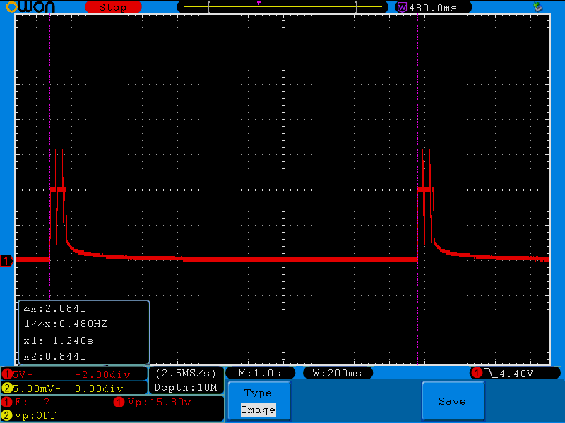
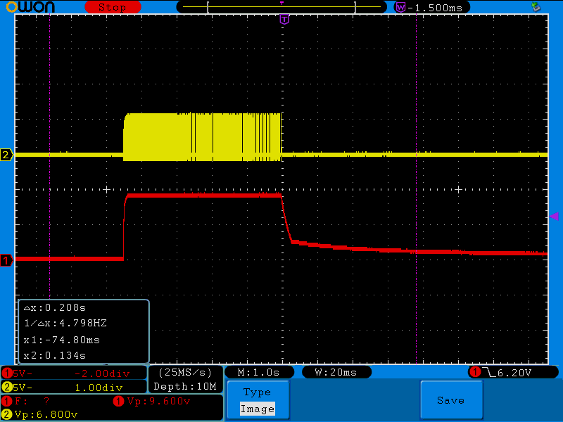
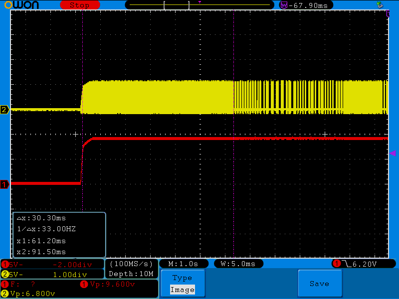
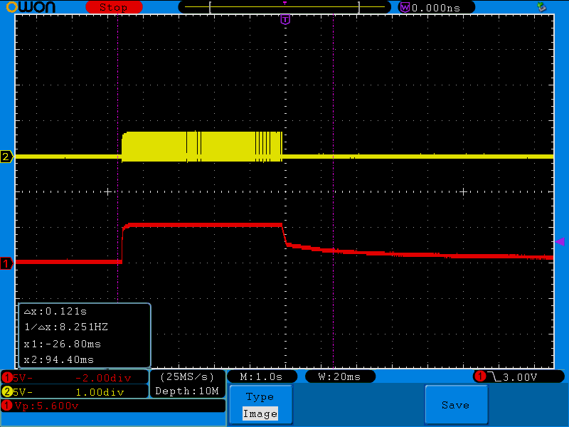
Due to the COVID-19 crisis I'm unable to use a lot of the equipment in the lab, therefor I'm using my very basic scope at home. When I measure on the Rect pin, I see the following result. My conclusion is that I receive the packages from the Tx, but it is enable to start the energy transfer. I experimented with changing the capacities a bit. But still no improvement. Does somebody have some suggestions?

Below my schematic, please note that the values of the capacitance's have been changed. For the new coil!

C101 = 47nF  50V  +-10%  SMD0603  X7R
C102 = 15nF  50V  +-5%   SMD0603   X7R
C103 = / (open)
=>  62nF

C104 = 1nF  50V  +-10%  SMD CERAMIC  X7R
C105 = / (open)
C106 = / (open)

'Old' working Qi Rx coil: Abracon AWCCA-38R32H09-C01-B 11,1µH 260mOhm

'New' not working Qi Rx coil: Wurth Electronic 760308101214 26µH 420mOhm

  • Hello

    Thanks for the info and scope capture.  But it is hard to say what the RX is doing.

    Is the time base 10ms / div, the pulse duration looks short?

    If the V/Dis is 2V then RECT is running high?

    Try taking a closer look at the start up, see attached.

    Looking at the RX coil they are very different---Old coil is large 39mm X 33mm with L=12uH the new one is 19mm Round with 26uH.  

    Tuning on the new coil should be about 100nF for C101+C102+C103.

    5123.bqTESLA FAQ--Start up.pdf

  • Hi Bill,

    My appologies for the late response, last couple of days I had other priorities. Apperently there is a mistake in the silk of the board. Therefor I was measuring on the wrong pin. Now I found the real TP2 on the board.

    Meanwhile I also changed my 62 capacitance of C101+C102+C103 to 100nF instead of 62nF. Afterwards I captured the screen, now I get this:

    Can I conclude that my Vrect is running high now. I see 10V start pulse and peak up to 16V (my capacitor is only 16V rated). What should I do, reduce C101+C102+C103 somewhere inbetween 62nF and 100nF? Or should I address C104+C105+C106?

  • Hello

    This is better but still not clear what the system is doing.

    We should see the RX communications on the RECT voltage, about 40mS after start up the RX should reply.  But this does not look right.

    Try checking the COMM1 or COMM2 pin, look for the communications packet.

    Another thing to try is reducing the communications capacitor value.  With larger L coils the 22nf value is a little large.  Good value is 10% to 15% of C104+C105+C106.  

  • Hi Bill,

    So I changed C104+C105+C106 to 150pF instead of 22nF. It is still not functional.
    I now also captured COM2 signal to view the packets. I wasn't sure what you wanted to see, so didn't go to much in detail.

    Red: Vrect (TP2) ==> +/- 9V  and after 900ms it stops.
    Yellow: COM2 (measured at C110).

    Here you see that the communications stops and the Vrect as well.

    It is very difficult to view the actual data. I also don't know what I'm looking for. Do you learn something from this?

  • "Red: Vrect (TP2) ==> +/- 9V  and after 900ms it stops." -- Bill J -- 9V is too high something is wrong, you should be 2.5V to 5V.  

    "So I changed C104+C105+C106 to 150pF instead of 22nF"--- Bill J -- For the C104+C105+C106 = 62nF then and comm cap of 22nf would be too large, need to reduce it to about 15% or 10nF..

    But the scope capture is pretty good and we do the the RX respond and send first packet in the start up sequence, Signal Strength.  BUT the TX does not decode it and turns off power.

    The depth of modulation does not look that great even with a 22nF capacitor.  I would expect it to be over modulated and causing problems but it is under modulated.

  • Hi Bill,

    My apologies! I confused a few things:

    C110 and C109 (COM capacitors) were 22nF and as you suggested I reduced it. C104+C105+C106 is 1nF so setting it to 10 to 15% means that I should reduce it to 150pF instead of 22nF.

    Originally C101+C102+C103 was 62nF and you suggested to increase it to 100nF instead.

  • Hello

    OK-- sounds good.

    Lets focus on the RECT voltage at 9V -- increasing the coil to coil distance should bring the voltage down.

  • Hi Bill,

    As suggested by you I played a little with the distance. I see that Vrect is reducing while increasing the distance. It goes quite fast actually. I used a wooding sheet of 2mm thickness to reduce it to around 6,8V. I check with different voltages, but the pattern remains the same. It suddenly stops.

  • The system has a lot of gain and I am surprised it is generating this much voltage.  What does the OLD system RECT look like?

    Something to try --- reduce the coil L value by removing turn from the inside.  But you would need an LCR bridge to measure L vlaue.

  • Hi Bill,

    Thanks for all the suggestions so far. But I'm not really getting where you are heading to with the 'reducing coil windings'. I'm looking for a replacement coil, not for a replacement coil I need to customize in order to get it to work. Having another stuffing on the board is something I can deal with.

    At this point I don't know what to do to move forward.