This thread has been locked.

If you have a related question, please click the "Ask a related question" button in the top right corner. The newly created question will be automatically linked to this question.

UCC27524: drive 2 IGBTs in parallel

Part Number: UCC27524

Hi,

my customer is connecting INA and INB of UCC27524 together, and they are driving 2 IGBT's in parallel.

They wonder which scheme is better:

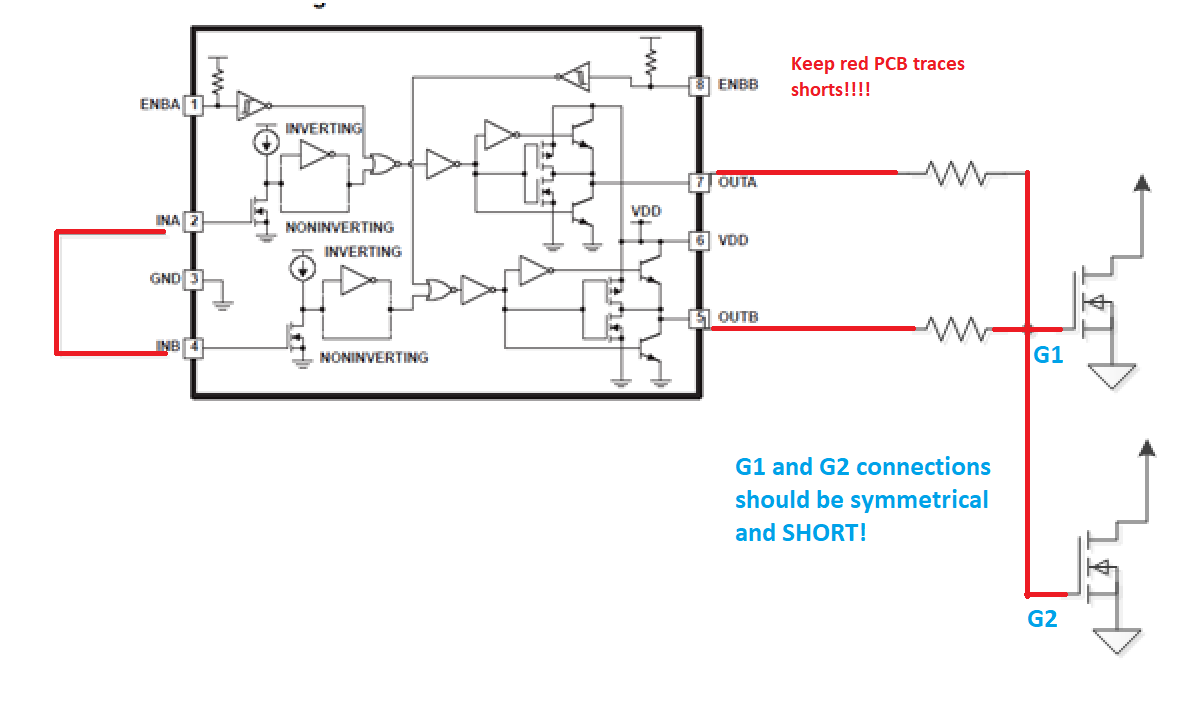
1. Connect OUTA and OUTB together at the device side and route one wire to 2 IGBT's gate side.

2. Connect OUTA to IGBT 1's gate side, Connect OUTB to IGBT 2's gate side.

Which is better? Or do you have better suggestion?

And in the related post, it's said

The UCC27424 is better suited for connecting directly in parallel due to the bipolar/FET output structure, and the switching times are a little slower.

Why bipolar output structure is better suited for parallel connecting?

  • Hi Howard,

    Can you please give a bit more details about the application as the better scheme will dependent on your application requirements.

    From a driver standpoint, there are several considerations for both schemes that I will highlight.

    1. The driver has 1ns delay matching allowing to minimal delay mismatch at the gates. This scheme will require matching resistors on both OUTA and OUTB before shorting as shown below. In this case, total peak gate current = 10A (assuming little gate resistance) to share between 2 IGBTs. Mismatch from asymmetrical PCB traces will increase risk of shoot-through on the IGBTs and/or drivers.


    2. The 2nd scheme will drive each gate separately through the two 5A channel drivers. Minimizing OUTx to gate connections and symmetrical PCB traces will reduce ringing and risks of shoot-through at the gates.

    Regards,

    -Mamadou

  • Mamadou,

    could you please tell me

    Why bipolar output structure is better suited for parallel connecting?

  • Hi Howard, 

    I am not sure where this is from but our drivers output stages features both bipolar output structure and MOSFETs based but in both cases, we're able to parallel the channels while taking care of the important considerations highlighted in the datasheets.

    Regards,

    -Mamadou

  • Richard Herring answered in the related post:

    The UCC27424 is better suited for connecting directly in parallel due to the bipolar/FET output structure, and the switching times are a little slower.

    For connecting driver channels directly in parallel we recommend the UCC27424 over the UCC27524.

  • Hi Howard, 

    Thanks for the clarification.

    The response entails connecting the 2 OUTx pins without gate resistance. When connecting shorting the OUTx channels without resistors and delay mismatch on the output, shoot-through is possible as referenced on Figure 29 in the datasheet.

    With the recommendations, you may use 524 for its higher peak current rating and wider gate drive voltage 20V max while 424 is also an option though the VDD range 16V (max) may not be high enough to accommodate IGBTs.

    Regards,

    -Mamadou