This thread has been locked.

If you have a related question, please click the "Ask a related question" button in the top right corner. The newly created question will be automatically linked to this question.

UC3875: Driving transformer

Part Number: UC3875
Other Parts Discussed in Thread: UCC28951, UCC28950, UCC27324, UC2875

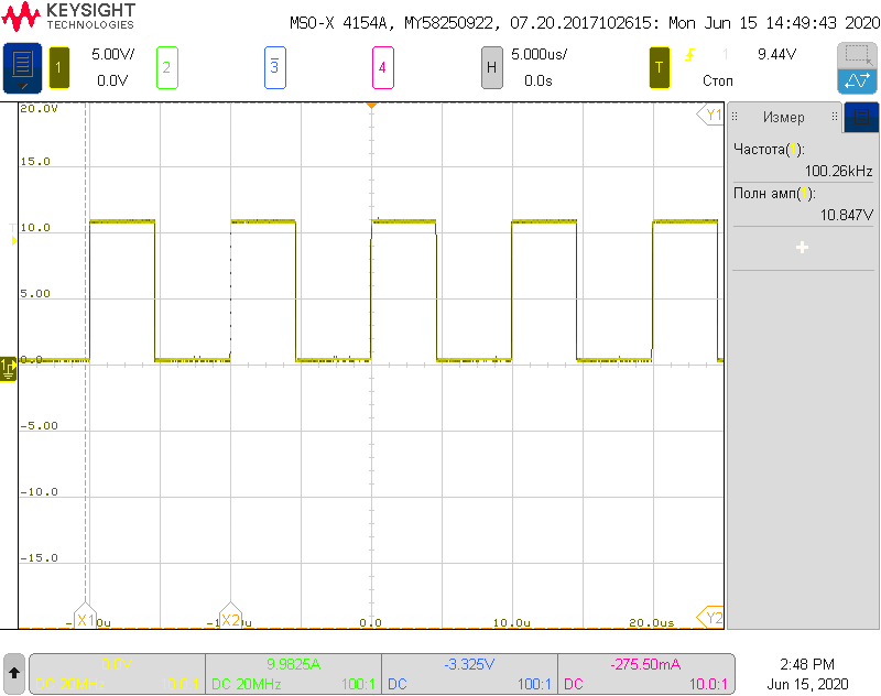
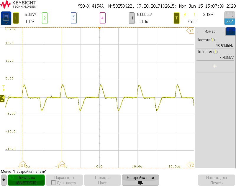
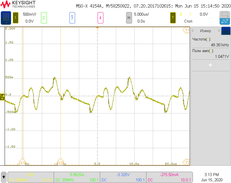
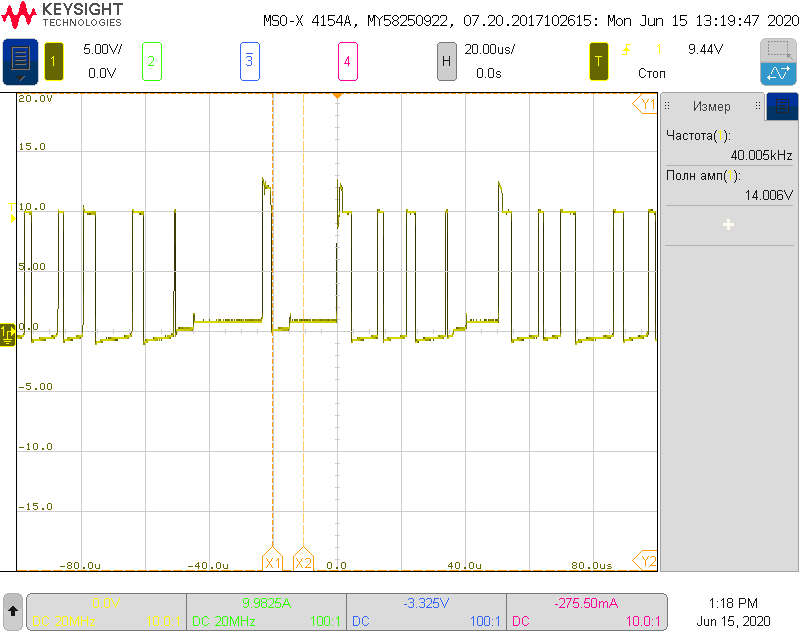
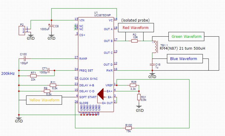
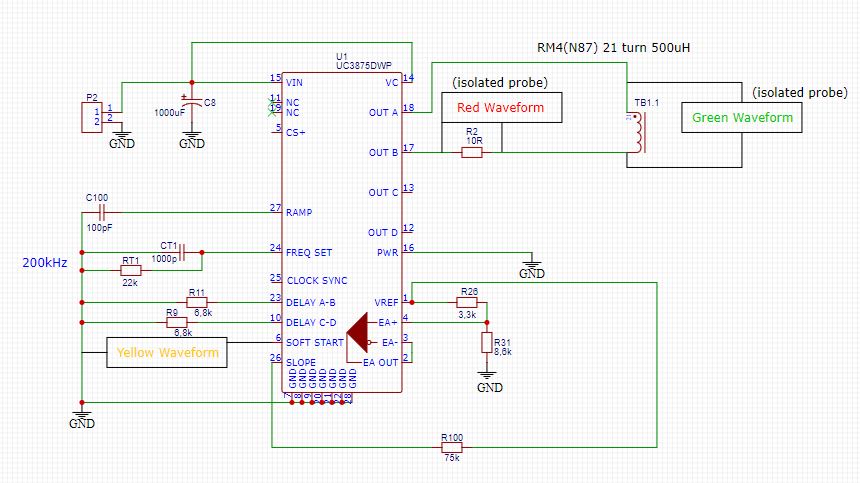
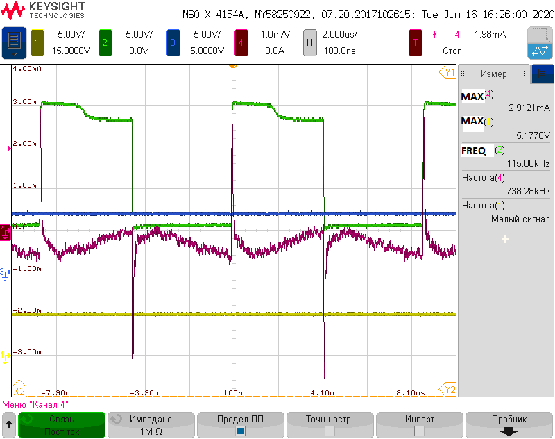
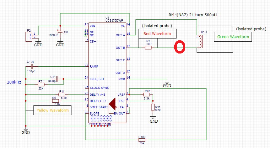
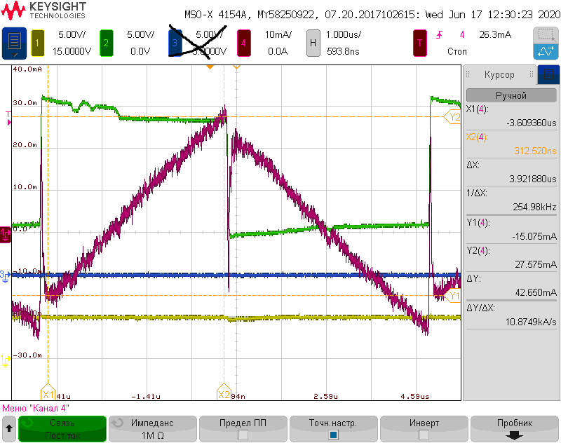
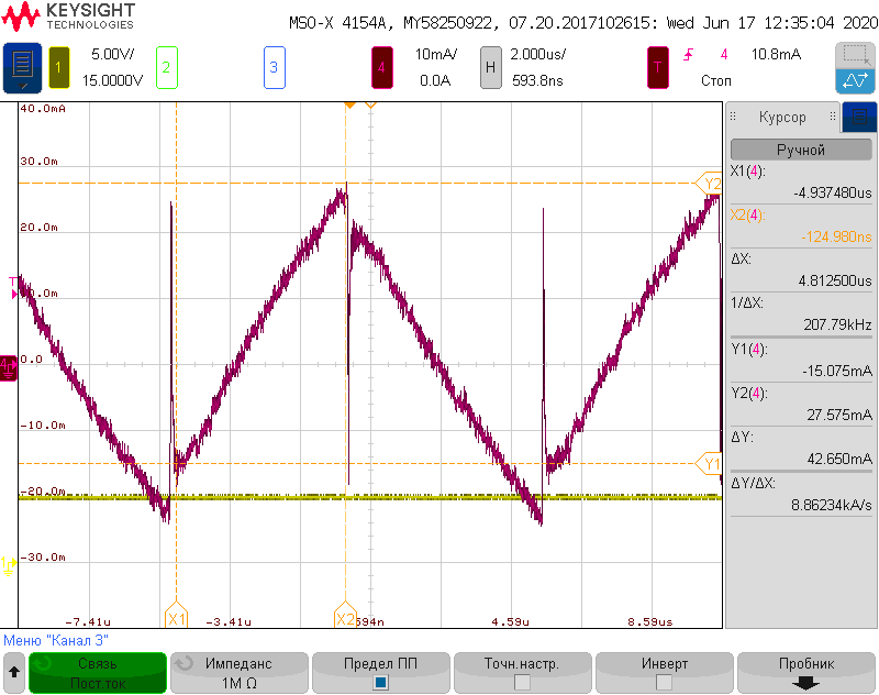
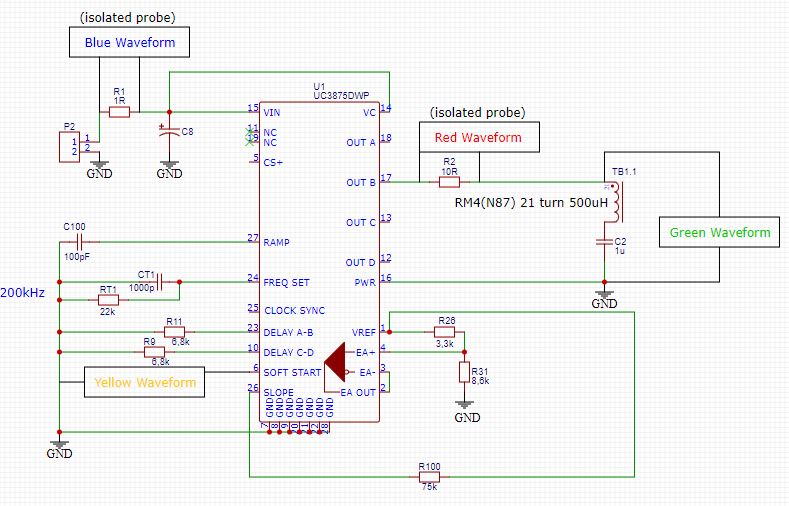
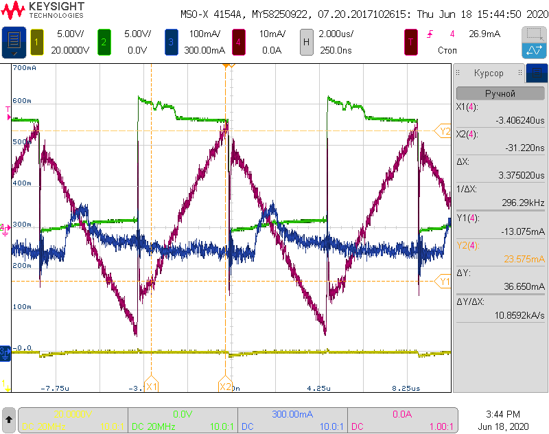
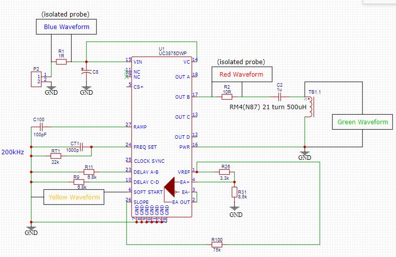
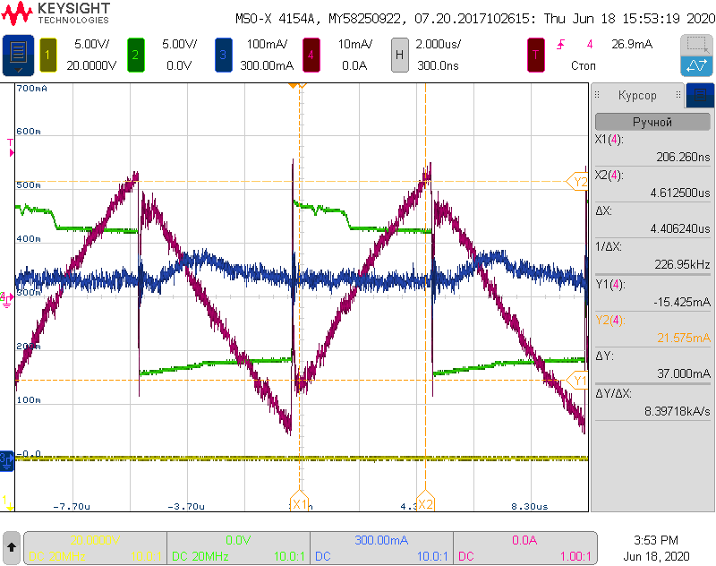
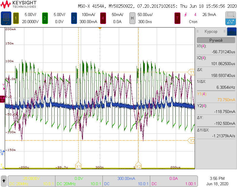
Hello! I an working now with PSFB using UC3875 and i know, it is quite old part but I have them in stock and I would like to use them, moreover, the question is more theoretical. I got question about MOSFET driving transformer configuration. I already have 4 transformers available and I want to control each transistor separately, as in the figure. But I ran into a problem when I connect only one channel (B), the current consumption increases significantly to about 180 mA (even if secondary of TB1 totally disconnected from QB1 R5 and R4 missing). When you connect all four channels instead, the PWM signal at the transformer outputs collapses. What could be the problem?

Transformer parameters are follow: core RM4, N87 material, ratio 1:1, Np=Ns=21 turn. Supply voltage 12VDC

  • Hello Vasily

    It may be an old part but it should still work :-)

    Can you measure or calculate the magnetizing inductance of the gate driver transformers and so figure out what the magnetizing current should be and compare it to what you actually get.

    At 200kHz the OUTx lines will run at 100kHz. I'd expect that the magnetizing inductance of the transformers should be between about 1mH and 2mH.

    The next thing to look at is the Volt*Sec product - assuming you are running off a 12V VC then the transformer will see about 12V*5us worst case. Because of the series capacitor, the resulting flux swing in the transformer will be centred on 0 and it will see 0.5*12V*5us in each direction. Calculate the volt second product of the transformer - anything greater than about 45Vus would be ok. You could put the capacitor in the return side of the trans former and measure the voltage across the transformer during switching and infer the current from the dv/dt rates.

    You could try adding a separate driver between the OUTx and transformer - UCC27324 would be a good choice - it's used on the EVM for the (newer) UCC28950/UCC28951 EVM.

    Let me know how you get on - post some waveforms if you can, especially if you can measure the voltage across the dc blocking capacitors.

    Regards

    Colin

  • Hello Colin

    Thank you for respounce! Datasheet says, that for RM4(N87) core AL value is 1100 nH/N^2. So, if i have 21 turns on primary side L=1100*10^-9*21^2=485uH. Therefore magnetization current will be: Im=U/(wL)=6/(2pi*100*10^3*485*10^-6)=0.0197A=20mA. So everything should be ok if my math is correct. Here is some more information: if I disconnect all the transformers (I remove DC-blocking caps), then the PWM controller consumption is 43 mA @ 12 VDC. And at the outputs a nice and clean PWM signal with 50% duty. As soon as I connect one of the transformers, say B, the current consumption becomes as much as 180 mA (the limit I set). The strange thing is that if I connect one more output (D) to the transformer, then the consumption will even decrease slightly. Could there be a gap in the fact that the outputs of the controller are loaded asymmetrically, or should everything work this way? By the way, is there nothing wrong with the connection that I drew? The datasheet  says that you should connect one winding between outputs A and B. But I think that what is shown in my schematic should also work well. On Monday, I will continue to solve this problem and provide some waveforms to make it more visual. Thanks again.

    Regards

    Vasily

  • Hello Vasily

    If you drive both ends of the transformer then the voltage across the blocking capacitor will be zero (ideally). Driving only one end of the transformer should be ok except that the initial transients as the blocking capacitor charges up to VCC/2 will be more severe than in the double ended case. It could b that this initial transient is large enough to cause problems that persist as the controller continues to operate.

    I really don't know why your circuit is behaving as it is but you might like to try driving the transformer double ended. (OUTA and OUTB: OUTCand OUTD)

    Please let me know how you get on - I'm interested to know.

    Regards

    Colin

  • Hello Colin

    Today i tried to connect two new transformers (i made two new, in order to make sure that there is no short circuit in old transformers) i connected them both to the OUT AB and CD but situation is not changed much. There is just no stable PWM at output (but current consumption around 150mA). The IC is obviously in some kind of protection. There is no stable voltage on soft start pin (just some noise), hence no voltage on EA out. As soon as i disconnect load from IC outputs it seems to work fine (soft start voltage also rises to 5V without any problem at no load) - see waveform on OUT B with no load: 

    I also connected 10R resistors in series with transformers to get a current waveform, but it changing time-to time. Here is two waveforms on 10R series resistors when only one of the outputs: OUTB or OUTD connected to the transformer at the same time:

    OUTB only

    OUT D only

    Here i connected all of the 4 outputs to the transformers, but i removed all components on transformer secondary (no any load on secodary) and total current consumptent droped to around 80 mA but there is still no any PWM at output (only some hearable noise from transformers). Here waveforme before c16

    Tomorrow I will try to load the chip with a purely resistive load - a potentiometer and see when the problems begin. I also have such a chip in the DIP case, I will try to assemble it on a breadbord and load it too, for comparison. By the way, 1 uF sireal cap is a good value, there is should not be any problem with this?

    Regards

    Vasily

  • Hi Vasily

    The first waveform showing the current in the 10R resistor looks reasonable, 4V in 10R = 400mA.

    I wonder if the controller is hitting it's UVLO point - the OUTB waveform is about 11V which is not much greater than the UVLO point at 10.75V (11.75V max)

    How about you try to run the controller from a greater supply voltage - you could try 15V for example.

    A 1uF cap in series with the transformer is a good choice.

    The SS pin should start at 0V and then ramp up smoothly (9uA into 0.1uF) to 5V - it will get pulled down if there is a fault (over current, UVLO etc)

    If you do breadboard the DIP version of the controller - do take care to make the ground connections from the various components to the IC as short as possible.

    Let us know how you get on.

    Regards

    Colin

  • Hi Colin!

    Today i made UC3875 on a breadboard and it seems to work well at no load condition. Frequency set also 200 kHz and on OUTx i see 100 kHz PWM. I checked OUTB with pure resistive load, and it's doing good up to 1 Amp (not checked any further). Next thing i made a transformer with only one winding (primary), RM4 core N87 material, 21 turn, 500 uH measured induction and connected all it in such manner: 

    Results:

    Current consumption starts from 300 mA (limit) and then slowly drops to around 160 mA@15VDC in roughly one minute. PWM controller gets pretty hotty! 60-70 ~deg.C

    Next configuration i made is to connect my "transformer" to out A and B, please see picture below:

    Result:

    As SS voltage LOW, IC didn't started-up.

    In the third experiment, I replaced RM4 N87 500uH (21 turns) with RM8 N87 5 mH (40 turns) and connected everything in the same way as the first circuit. Everything seems to work fine. Please see some waveforms:
    I can not understand why with RM4 it does not work properly. Isn't an inductance of 500 μH enough? The current does not even come close to a large value.
    Regards
    Vasily
  • Hello Vasily

    I'm glad that you made some progress. It looks like you are running the controller from 15V so that is good.

    I would have thought that 500uH would be enough - although maybe a bit on the low side of optimum.

    An RM4 core has a cross section of 11mm^2 so I'd calculate a peak flux density of B = (V*t)/(N*A) = (15V*5us)/(21*11mm^2) = 325mT which is fairly high but it's centred on 0mT so +/- 160mT which is fine.

    A quick sim shows that a 500mH magnetizing inductance should take about 21mA of current at 100kHz when driven from a 15V square wave.

    You should double check the inductance you are seeing on the test board by using the L = V Dt/Di relationship. I tried it but got strange answers, perhaps because i was using the wrong vertical scale for the current. Anyhow, you should get a good agreement between the calculation and the measurement you took on the inductance meter.

    You should add a DC blocking capacitor on the double ended circuit - 1uF will work well.

    I'd repeat the calculation for the inductance for the case below -

    Regards

    Colin

  • Hello, Colin!

    I double checked my connections and, D'oh, I forgot that my diff probe (waveform on 10R) has 10: 1 ratio! I'm sorry to confuse you, it should be 10 mA / div instead 1 mA / div in all previous waveforms. It's actually ~ 280 mV peak at 10R resistor which is 28 mA peak. I reconfigured my settings and now it should be the right ratio. In all new waveforms it's the correct settings for current.

    Today I repeated my first configuration with a transformer from OUTx to GND on a breadboard and on my PCB and the results are pretty close.

    Setup:
    Results:
    On breadboard (with my new hand made RM4) please ignore CH3,i forgot to turn it off:
    On PCB (with original RM4) markers are little bit displaced, sorry:
    I calculated inductance as you advised and got following results: first case (breadboard) dI=42,7*10^-3A; dt=3,92 * 10^-6 s, L=U*dt/di=7,5*3.92*10^-6/42.7*10^-3= 689 uH vs (500 uH measured) If we take into account the voltage drop across the 10R resistor and in the IC, the result will be closer to the truth.
    Second case (PCB)   
     dI=40,7*10^-3A; dt=4,4 * 10^-6 s, L=U*dt/di=7,5*4,4*10^-6/40,7*10^-3= 811 uH  vs (600 uH measured)
    Problem: SS voltage is 5V and it's somehow works. PWM controllers current consumption is near 200 mA in both cases and it is hot! Definitely something wrong with this!
    P.S. You mentioned "optimum" inductance in your last reply, what is optimum value and how I can estimate this value. Thank you!

    Regards

    Vasiliy

  • Hello Vasily

    Soft start at 5V is ok - the data sheet mentions 'about 4.8V'

    500uH is a bit low, 1mH is more usual for a gate driver transformer but as I said, 500uH should be ok. The transformer should take about 20mA RMS and add in about 30mA for the VCC current for the IC for about 50mA - which is well below the 200mA you are seeing.

    What happens if you put a driver IC between the UC2875 and the transformers - UCC27324 would be a good choice - we used it on the EVM for the UCC28950 https://www.ti.com/lit/ug/sluu421a/sluu421a.pdf?ts=1592481098393&ref_url=https%253A%252F%252Fwww.google.com%252F

    Regards

    Colin

  • Hello Colin!

    I understand that 5 volts is the normal level at the SS pin. The reason why I show this level in my oscillograms and refer to it is that if it is LOW, I conclude that the IC has gone into protection mode and you should not expect a stable PWM signal at the outputs. (Note this at last waveform)


    Without transformers, the chip consumes only 43 mA @15 VDC.When a transformer is connected, for some reason I do not understand now, the consumption increases significantly to 200-300 mA while the current through the transformer corresponds to the calculated value of ~ 20-30 mA. For clarity, I attach measurements of this input current. Please note that it is more or less constant.

    Setup on breadboard:

    Measurements:

    Then I repeated everything on the PCB, setup (Please pay attention to a different location of C2 (I can not measure here differently))

    Measurements:

    If I connect 2 transformers in this way (output B and D), then the IC stops working. Pay attention to the level of the SS (yellow) signal. Here are the waveforms of this process.

    Colin, thank you very much for the information about the driver ICs and the EVM. I am familiar with the datasheet on the UCC28950 and, if possible, I would use it in future projects. It has excellent documentation and is easy to use. I am pretty sure that if I use a driver ICs in this configuration, everything will work fine. Unfortunately, I do not have these drivers available now to demonstrate the result to you and buy them here in the near future can be problematic. Moreover, if I had the opportunity to use external drivers, I would choose another, more modern PWM controller without built-in drivers, such as the same UCC28950 that you recommend.
    One of the goals of this development was to use a minimum of external components and, if possible, get along with driving transformers and IC's integrated drivers. Unfortunately, I already have several PCBs designed for installing RM4 and UCC3875 so in case of a significant change in the circuit, I will have to throw them in the trash. Therefore, my task now is to make the UC3875 work.

    Regards

    Vasiliy

  • Hello Vasily

    It's been a while since the last post on this thread so I'm going to close it. Please feel free to open a new related thread if you need to continue this conversation.

    Regards

    Colin