This thread has been locked.

If you have a related question, please click the "Ask a related question" button in the top right corner. The newly created question will be automatically linked to this question.

LM3481: Can I use LM3481 for a system where no-load status can occurs?

Part Number: LM3481
Other Parts Discussed in Thread: LM3478, DRV8825, , LM5155EVM-BST, LM5155

I have made a step motor driver board with LM3478 to supply 24v from 12v input.

LM3478

The problem is that a user can power the board without the stepper connected board which drive the board to no-load status on LM3478. Just 2 stepper motor drivers(drv8825) are connected to 24V.

LM3481

After LM3478 circuit is broken and burnt, I googled the problem and found LM3478 is not a proper choice for this situation.

It seems like LM3481 might works with the following feature as stated in the datasheet, but I am not sure at all if this is the right one for my situation.

From the first page of the datasheet: "Pulse Skipping at Light Loads"

Will LM3481 work for my situation? If not, what are the other popular chips usable for my system?

These are the system requirement.

Input: 9v~18v

Output: 24v, 1~2A

  • Hi Chanoh,

    Thanks for reaching out with your questions and for considering the LM3481 and LM3478.

    I am curious at why you think the LM3478 would not work of the application? At light load the LM3481 and the LM3478 are both going to have pulse skipping at light loading conditions. The purpose of this is to increase the efficiency at light loading conditions.

    If you do not want the increase ripple on the output at light load please use a device similar to the LM5155. You might want to take a look at the LM5155EVM-BST (boost evaluation module) as it is pretty much the same specification as your application.

    Please let me know if you have any questions.

    Thanks,

    Garrett

  • Hi Garrett,

    Thanks for the comments.

    So, you mean the no-load condition should not be the reason for LM3478 self-destruction? The ripple is fine.

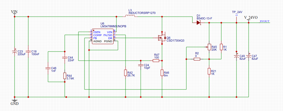
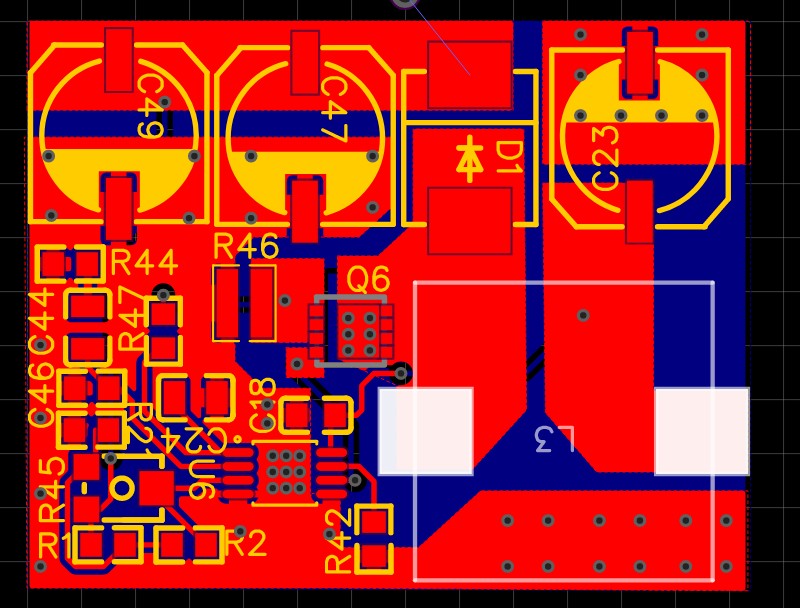
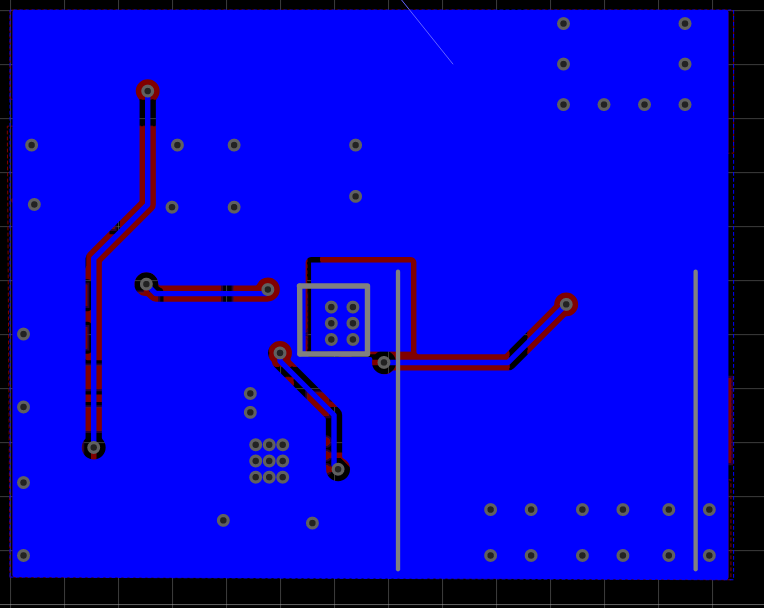
    I am attaching the schematic and layout for your reference.

    R1, R2 is not used

  • Chanoh,

    The ripple on the output voltage should not damage the LM3478.

    Is R1 in your schematic really 1kOhm? This seems too small for the top feedback resistor. Please follow the datasheet on how to select the correct feedback resistor values.

    Thanks,

    Garrett

  • Hi Garrett,

    Thanks for checking. R1 and R2 are not mounted. They are for test purpose only without R45. From the schematic and layout, do you see any other reason that my board should fail?

  • Chanoh,

    What is the operating condition when the LM3478 is being damaged? Is it damaged on the initial start-up? Or only during a certain operating condition?

    If the device switching please capture the switch node voltage, the VIN pin voltage and the FB pin voltage.

    Thanks,

    Garrett