Because of the holidays, TI E2E™ design support forum responses will be delayed from Dec. 25 through Jan. 2. Thank you for your patience.

This thread has been locked.

If you have a related question, please click the "Ask a related question" button in the top right corner. The newly created question will be automatically linked to this question.

TPS92515: Review schematic and some inquiry

Part Number: TPS92515

Dear Sir,

I'm using TPS92515 and Our R&D process is Pre-Production.
I want to get your review about schematic and some question.

1. Our test condition
  -. Vin range : 12V ~ 24V
  -. PWM Frequency : 20KHz
  -. LED Vf : 2.7V(min) / 3.2V(typ) / 3.7V(max)
  -. LED forward current : 1A

2. Our inquiry
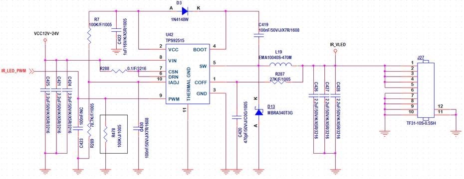
  -. Review schematic.


  -. Is there no problem to use PWM frequency 20KHz? or
     What's the side effect if we use 20KHz? or
     What is your strongly recommendation about PWM frequency range?
     We already checked Standard PWM frequency range from 100Hz to 10KHz on the data sheet.
     But, there is no maximum frequency spec. about this product except any comment about high frequency.

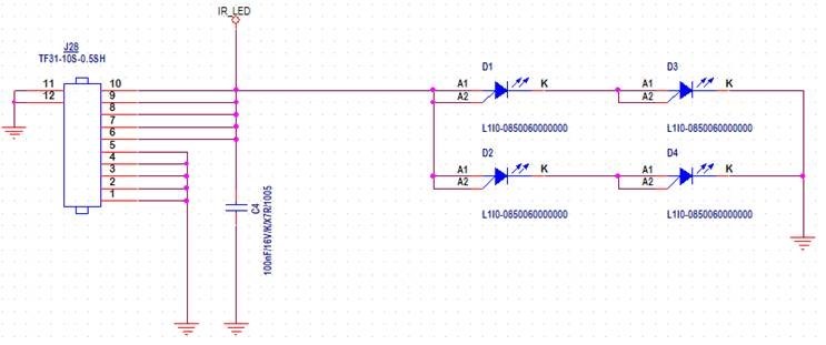
  -. Our LED configuration is 2 parallel type. You can see it on our schematic.
     LEDs intensity is changed when our Vin range is changed from 12V to 24V.
     At this configuration, can this happen?

  -. Could we use it like 2 parallel type about LED configuration?
     If not, do we have to use serial type not parallel?

  -. Audible noise has occurred at TPS92515 block.
     Could you give us debugging point and PCB artwork guide? or
     If we use PWM frequency range from 100Hz to 10KHz, can audible noise occur at this part?

Could you please send us your reply ASAP.

Best Regards,
Michael

  • Hello Michael,

    I calculated your design parameters from your information.  I used Vled at 6.4V two LEDs in series per your schematic.

    Fsw at 12V = 216 KHz

    Fsw at 24V = 340 KHz

    di/dt inductor (peak to peak ripple) = 0.294 Apkpk

    1)  You can use PWM frequency of 20 KHz however you will run into issues with inductor slew rate.  At 12V input it takes 18.5 us to reach the peak current threshold, at 24V input it takes 5.9 us.  the period of 20 KHz is 50 us.  This means at 12V input duty cycles of 37% or less will not reach peak current threshold, at 24V input below 12%.  At 12V it is near 50% duty cycle so the dimming will look nearly linear, at 24V it will not.  This also means there will be more light output at 24V than at 12V when PWM dimming at mid to lower duty cycles.  If you need more accurate dimming you should look at shunt FET dimming.  You can also improve this some by increasing the switching frequency and reducing the inductor value.  You just have to make sure that you don't fall below the minimum on-time requirement.

    2)  From your schematic you have four leds in a 2 parallel, 2 series configuration.  This is fine.  You will not be able to run all series due to 12V input voltage, you also will not be able to use this part if you place them all in parallel, 4A average.  LED intensity change is mentioned on 1) above.  This is due to the rise time of the inductor.  V = L * (di/dt).  V = Vin - Vled.  At 12V this is 5.6V (12V - 6.4V) and 24V it is 17.6V (24V - 6.4V), di is 2.2A, L is constant at 47 uH.  This means dt changes as mentioned above.

    3)  This has to do with how you are dimming, the inductor slew rate is causing the light intensity to change.

    4)  Audible noise is caused by di/dt, most likely the inductor or ceramic capacitors.  This requires trying different inductors, different inductor mounting to PCB or potting the circuit.  This is a common issue when PWM dimming.  You may want to look at shunt FET dimming.

    Best Regards,