This thread has been locked.

If you have a related question, please click the "Ask a related question" button in the top right corner. The newly created question will be automatically linked to this question.

UCC256403: Unexpected switching pattern in Burst mode

Part Number: UCC256403

I have been working on a 2kW battery charger project. I use UCC256403 as the main Power Supply Controller. I am currently testing at lower input voltage to ensure functionality in every mode before using the high voltage input. I observed some unexpected switching pattern in some Burst mode cycles. Below are the images of the various waveform at different pins.

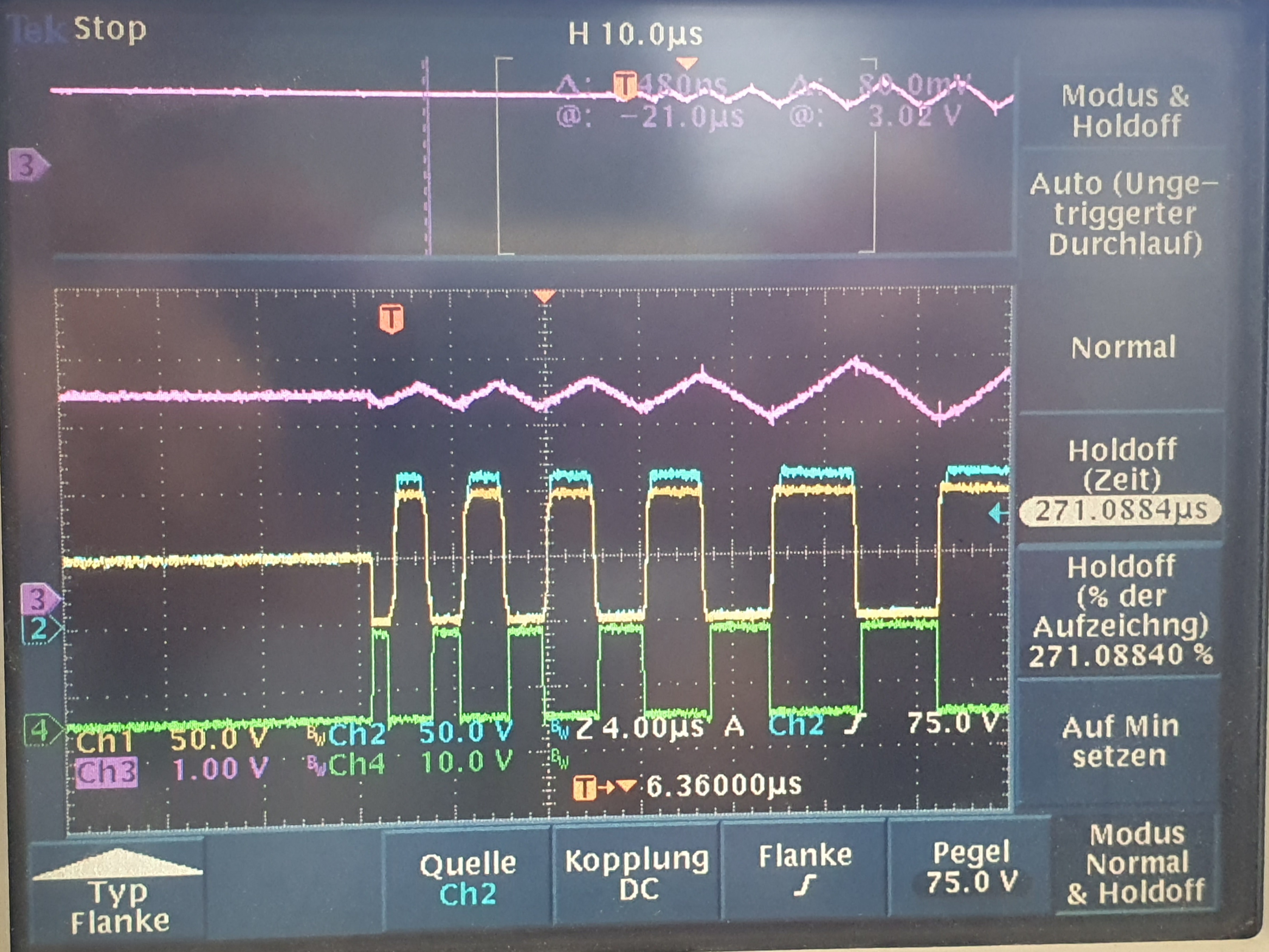
Ch1: HS pin                        Ch2: HO pin

Ch3: VCR pin                     Ch4: LO pin

Erroneous Operation: 

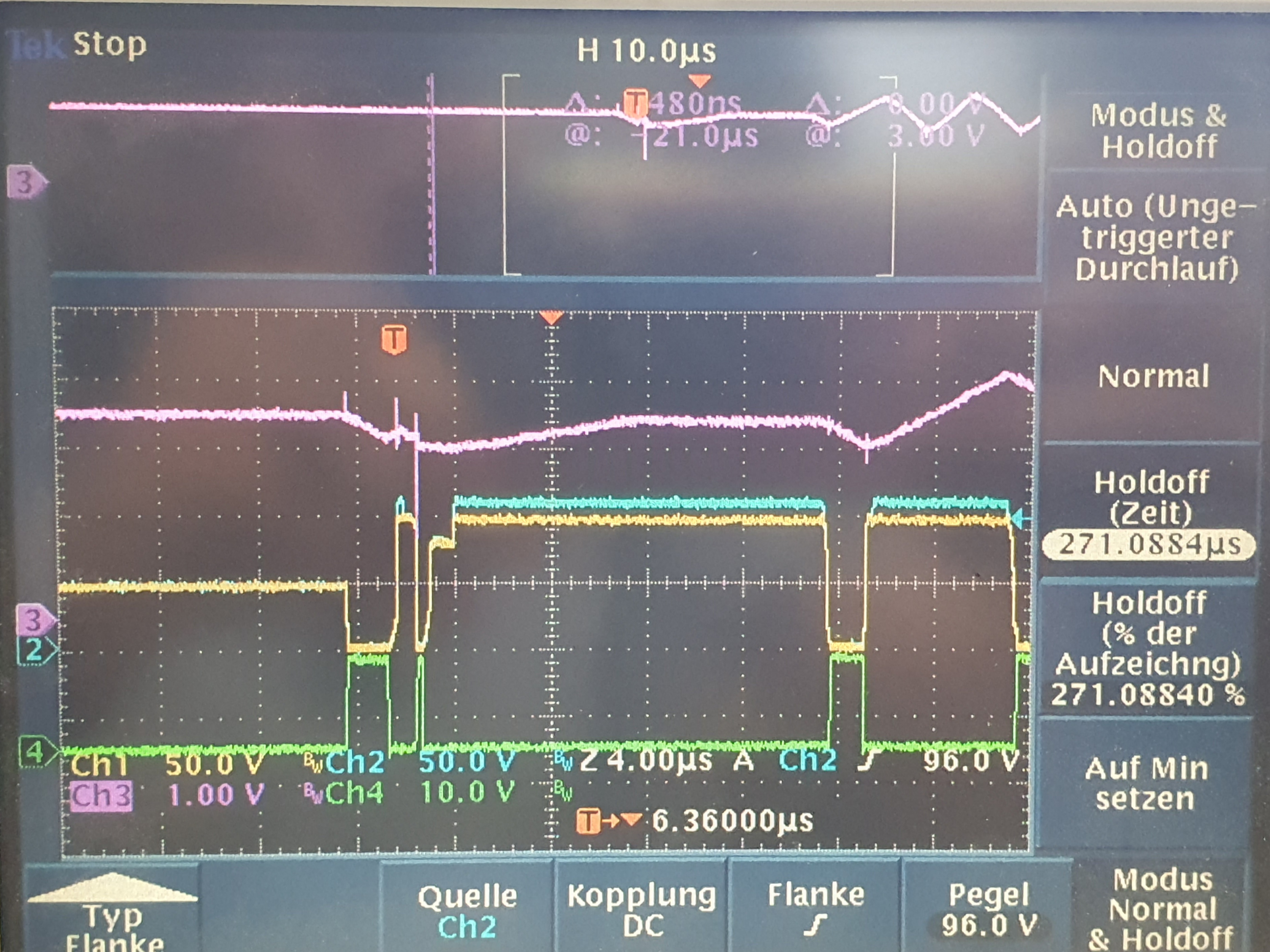
Expected/Normal operation:

Under Erroneous operation, Controller seems to turn of the upper MOSFET after approximately 250ns. I cannot seem to justify this behavior. It would be really helpful if I could get some support regarding this.

Thanks in Advance.

  • Hi,

    LLC converter is sensitive to the input voltage. Are you testing your converter in your specified input voltage range? What is your input voltage assumption when you design your LLC converter?

  • Dear Mr. Huang,

    Yes i agree that the LLC converter is sensitive to input voltage. But this is a scaled down operation with input and output voltages both scaled down. The converter is designed to operate at 390V nominal DC input voltage. The lower input voltage should not cause premature turn OFF of upper MOSFET. Since the switching has to be balanced in LLC, the turn ON times of upper and lower gates has to be similar. I would like to know under what condition does the Controller turn OFF the upper MOSFET prematurely.

    Edit: Similar effect is also observed at 390V DC input voltage.

    Thank You,

    A S Nagaraj

  • How did you design and scaled down your design to run at a lower input voltage?

    Do you have an EVM with you so you can compare each waveform on a similar scale down?

    Did you check your burst mode operation design and scale down as well? Did your converter trigger any fault?

  • By scaled down version i meant the output voltage and current are also selected that the LLC Tank gain/ operating region is similar to the nominal case. It is anyways irrelevant since this happens also at the nominal input voltage.

    I have an EVM but comparison to it would not yield any relevant information since the battery charger circuit and feedback loops are much more complex compared to just a Power supply. I also have a different layout. 

    Burst mode design depends on the load to input voltage ratio and as far as i know does not need to be scaled down.

    I think we are deviating from the main question here.

    Under what condition can the Controller turn off Upper MOSFET prematurely? How can the ON time suddenly jump from approximately 2us to 250ns? It would be really helpful to get this information because even with soft burst ON as per my design, the max. frequency must be well below 500kHz.

    250ns corresponds to 2Mhz.

  • Not sure if you see this from one of our experts.

    It looks like noise on VCR made the VCR waveform cross the VTH turn threshold early and this is causing the controller to turn off HO after only 250ns. The good waveform shows no spike/switching noise in the VCR waveform. Would also be interesting to compare the FB pin voltage between the good and bad burst patterns. I am wondering if the opto-coupler saturated and is causing the FBreplica to behave differently between the good/bad burst packets.

  • The FB pin voltage is stable in both cases. Optocoupler didnot saturate. I have additional external zener circutry. Well I agree that it may be that noise on VCR pin. I cannot seem to find the source of that noise. I solved this problem partially by setting the BMTH to BMTL ratio very high (0.95) and avoiding high frequencies. Seems to happen only at high frequencies. 

  • Can you review your layout to see any improvement to reduce the noise?

  • Layout is as optimised as it can be. Moreover this project is near end development stage. Any changes to the layout now is not practical. This layout worked fine till the last revision. Then we made some changes due to EMC issues. It initially used UCC265303. I switched to UCC256403 because the former would latch and stop switching when this case occurred. A layout change at this point is not feasible. Since the problem occurs only at considerably high frequencies, we will probably continue with the measures to avoid it. 

    Moreover I am not 100% sure whether the Controller turns OFF the upper MOSFET due to the noise or the noise occurs due to the premature turn OFF. It would have been beneficial if the controller had some blanking time to ignore these high transient noises. 

    Thanks for the response. We can close this thread now.

  • Ok, then let's close this thread.