This thread has been locked.

If you have a related question, please click the "Ask a related question" button in the top right corner. The newly created question will be automatically linked to this question.

LP5024: Trouble with getting LP5024 output.

Part Number: LP5024

Hi,

I have used LP5024 in my design to independently control LEDs for status indicator. I am able to communicate with the device. Configuration values are as follows.

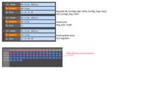
DEVICE_CONFIG0 = 0x40 (Chip_EN = 1)

DEVICE_CONFIG1 = 0x2E (Power save is off for development, Current = 35mA)

LED_CONFIG0 = 0xFF

BANK_BRIGHTNESS = 0x80

BANK_A_COLOR = 0x80

BANK_B_COLOR = 0x80

BANK_C_COLOR = 0x80

LED0_BRIGHTNESS = 0x80

LED1_BRIGHTNESS = 0x80

LED2_BRIGHTNESS = 0x80

LED3_BRIGHTNESS = 0x80

LED4_BRIGHTNESS = 0x80

LED5_BRIGHTNESS = 0x80

LED6_BRIGHTNESS = 0x80

LED7_BRIGHTNESS = 0x80

OUT0_COLOR = 0x80

OUT1_COLOR = 0x80

OUT2_COLOR = 0x80

OUT3_COLOR = 0x80

OUT4_COLOR = 0x80

OUT5_COLOR = 0x80

OUT6_COLOR = 0x80

OUT7_COLOR = 0x80

OUT8_COLOR = 0x80

OUT9_COLOR = 0x80

OUT10_COLOR = 0x80

OUT11_COLOR = 0x80

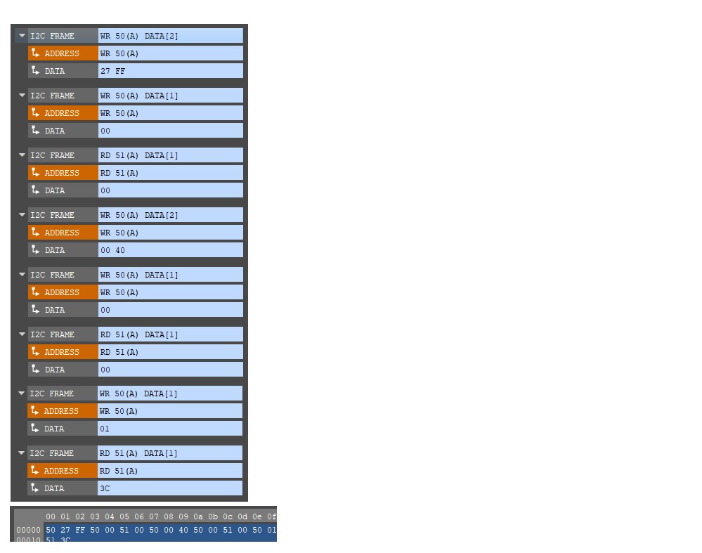
I am able to configure the registers and read them back. Need support on following points.

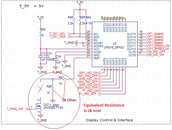
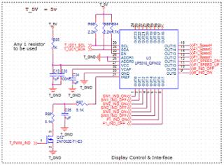
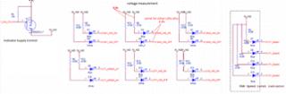
1. But once send OUTx_COLOR data values I am not getting any output. I am using LEDs in common Anode configuration as shown in the attached figure. Voltage levels seems to be fine as measured. Some of the screen shots are attached herewith for ref. I assume that I am passing some wrong configuration values

2. Please let me know where I am doing wrong. Also please share the values of the configuration registers for simple LED ON/OFF control. configuration for Status indicator.

3. For this resistor values in Iref pin what will be value of Iset? (If I use Riref = Kiref xViref/Iset, With MOSFET ON Riref = 5.1k+5.1k. hence Iset = 105x0.7/10.2k comes to be 5.147mA which is not sufficient to drive an LED.

4. Is there any effect of giving a PWM put at MOSFET at Iref pin using MOSFET as in the circuit.

5. what is the relation hierarchy of BANK_BRIGHTNESS, LED0_BRIGHTNESS and OUTx_COLOR registers?

Thanks & Regards

Gyanesh

  • Hi Gyanesh,

    Could you help to send some clear picture? I cannot recognize the words in them.

    1) I think your register configuration is OK.

    2) To off the LED, you could set brightness or color register to 0. Or here is a global off function in bit 0 of register 01h. 

    3) You need to check it in LED spec to see if 1.3mA is OK to drive your LEDs. To check if output pins drive current correctly, you could connect a power source which set as 2V to one channel and measure the current.

    4) I think it is OK as your design.

    5) Bank function could help to globally configuration all channels. When LEDx_Bank_EN = 1, the LP50xx device drives the LEDs in LED bank-control mode. LEDx would be controlled by BANK_BRIGHTNESS and BANK_COLOR registers. When LEDx_Bank_EN = 0, this group of channels would be controlled by LEDx_BRIGHTNESS and OUTx_COLOR registers. Both brightness register and color register control PWM of output. You could find details in Figure 9 and Figure 13.

  • Thanks Hardy,

    I will go through each point what you have suggested and will follow those steps. Meanwhile as you have requested Please find the schematic for better understanding of my project. Please let me know if any improvement required in the schematic.

    Thanks & Regards

    GyaneshSCH_V3_5_1 _ 03_Ind.pdf

  • Hi Gyanesh,

    I have no other concern of your design.

  • Hi Hardy,

    Thanks for the reply. I followed the steps as you suggested. Also I have made a few modifications to debug this chip as follows to change the current limit on IRef pin.

    Changes can be compared with the previous circuit I shared earlier.

    1. replaced 5.1k resistance with 1k ohm

    2. Disconnected another 5.1k resistance in IRef to make it open from the MOSFET control. 

    3. Replaced 1uF capacitor with another 1k resistance.

    4. Now effective resistance on IRef pin is 2k ohm as shown in the attached picture.

    But I can see that chip is still showing NOT Enabled even after giving CHIP_EN cmd. It guess it is going into shutdown mode (I may be wrong.).

    Please let me know what wrong I am doing.

    Thanks & Regards

    Gyanesh

  • Hi Gyanesh,

    Sorry that I was on vacation and did not reply you in time.

    If you can read all register value as your set, the device should be at normal or standby state. Could you help to measure the voltage on VCAP and IREF and also connect a power source which set as 2V to one channel and measure the output current?