This thread has been locked.

If you have a related question, please click the "Ask a related question" button in the top right corner. The newly created question will be automatically linked to this question.

BQ25703A: Power management forum

Part Number: BQ25703A
Other Parts Discussed in Thread: BQ25713

Hello Support Team

I am designing a power stage that has dual battery inputs, one rechargeable (3S) and a second non-rechargeable (2S)
- Note: only ONE battery is present at a time in the system.
- There is also a DC adapter input (5v~24v) for charging and system power.

According to the #BQ25703A datasheet, and if I understand correctly, we have 3 cases

  1. Adapter Only: the output of the charger (+VSYS) is regulated to the default minimum system voltage.
  2. Battery Only: the device is in battery supplement mode. +VSYS - Vbattery = VDS of BATFET.
  3. Adapter and Battery: if Vbattery > VSYS_min, then VSYS output will be regulated to around 160 mV above Vbattery when BATFET is off (no charging or no supplement current).

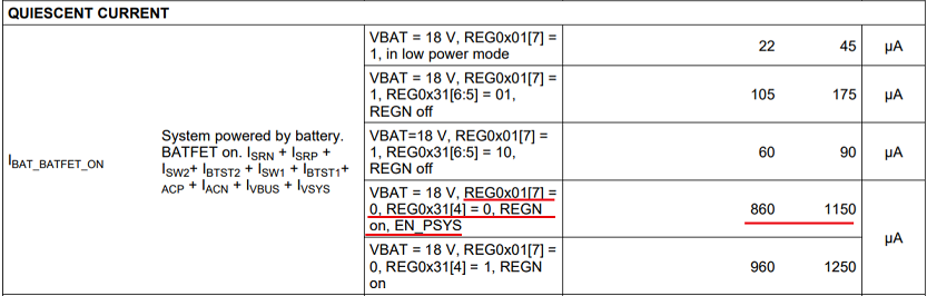
Now, I am looking at three ORing options below, and I have some questions pertaining to BQ27503A quiescent current consumption in the case when there is NO charger connected.  

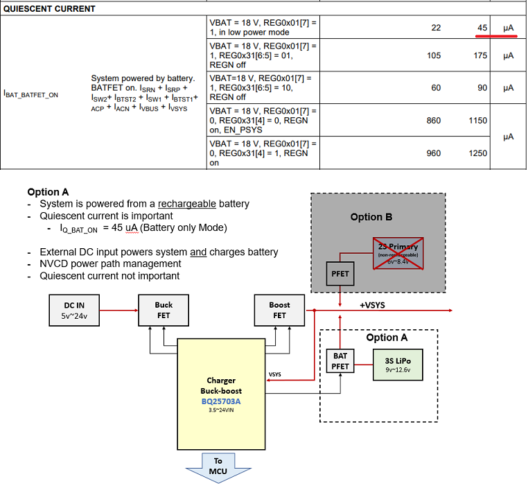
Option A: To minimize losses and save battery life, my first thought is to place the primary battery and control a P-FET after the #BQ25703A output at +VSYS.
The basic idea is to 

  • Force Charger in Hi-Z state
      > Drive CELL_BATPRESZ low to indicate battery removal 
      > Drive ILIM_HIZ Low  
  • Set VSYS_min = 9.0v,
  • If external DC adapter is connected, P-FET is turned-off and #BQ27503A regulates VSYS 

#1) Is it possible to power +VSYS from primary battery only, i.e. adapter is NOT connected and CELL_BATPRESZ = low?

#2) presumably #1 works, can you please advise on the correct steps to achieve lowest quiescent current?

#3) As per datasheet Iq_max = 45µA in low power mode, can you please confirm this is the same as #2 above?

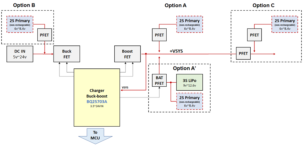
Option A': Since in our application, only a single battery is present, extending the concept,

#4) Is it possible to share BATFET path for the primary battery as well?

  • By forcing #BQ25703A into HI-Z state, according to datasheet BATFET can be turned ON/OFF via  BATFETOFF_HIZ  register - so this works when there is NO adapter

#5) Presumably #4 above works, what is the behavior of the BQ25703A when adapter is connected? 

#6) What are the correct settings to ensure BATFET remains OFF when adapter is connected?


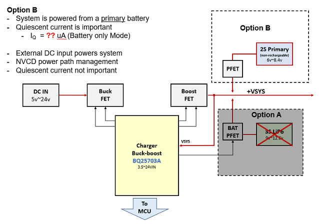
Option B:
 place the primary battery before the #BQ25703A in ORing configuration with the adapter. But the efficiency is reduced.
Alternatively, I looked at the #BQ25713 pass through mode (PTM) and it might just do the trick. 

#7) Can you please confirm quiescent current in PTM?


Option C:
 involves adding extra P-FET to isolate the #BQ25703A when no adapter is connected.
This seems the most promising approach for Zero Iq. though, the Iq savings may be diminished with extra circuitry required to isolate signals from the MCU.


Thank you for your support.


Best,
AJ

  • Hi AJ,

    Is key care about just the leakage current? I am in the process of reviewing the different options and will get back ASAP.

  • Hi Kedar,

    Thank you for quick response. It's not the leakage I am concerned about, it's more the quiescent current.

    In our application, the device operates from battery with 2 years life minimum requirement without the need to charge. For that reason, I need to make sure that the charger circuitry and ORing approach has minimum battery drain. 


    Best,
    AJ

  • Hi AJ,

    1. Forcing the charger in a HI-Z state when adapter is not connected, and disabling the BATFET in HI-Z mode will allow you to supply the SYS with your primary non-rechargeable battery, while reducing quiescent current
    2. In HI-Z mode converter will be disabled, with REGN LDO active, resulting in a low quiescent current mode without sacrificing on BATFET protection.
    3. Low power mode is enabled in battery only mode, resulting in the 22uA typ Iq and 45uA max Iq.
    4. Not possible to parallel the primary non rechargeable battery at the charge output
    5. See 4.
    6. Enable HI-Z mode and in HI-Z mode, disable the BATFET
    7. Not recommended to diode OR the primary battery with the adapter. PTM is intended to directly support SYS from adapter, and in such a configuration the quiescent current is not a concern, as the adapter is able to directly supply the SYS, and quiescent current is not a concern when adapter is present. In PTM there is still switching, as gate drive to drive the HIDRV1 and HIDRV2 has to be enabled for PTM (increased quiescent current) as well as occasionally turning on the LORDV1 and LODRV2 to refresh the bootstrap capacitor, which is used to drive the HIDRV1 and HIDRV2. This increased quiescent current is not desirable if you are using the primary battery as the input source.
    8. This will be the best option for Iq, as it isolates the quiescent current from the IC with the PFET in the SYS path. Note that apart from the increased BOM, layout size and cost of the additional PFET, the Lipo discharge/charge current through the extra RDSon of the PFET would result in a little extra power loss and reduced efficiency, when supplying SYS.

  • Hello Kedar,

    Thank you for the detailed response. I think I get it, though I am a little unclear on answers for 1 and 2 below:


    #1) Is it possible to power +VSYS from primary battery only, i.e. adapter is NOT connected and CELL_BATPRESZ = low?
    Forcing the charger in a HI-Z state when adapter is not connected, and disabling the BATFET in HI-Z mode will allow you to supply the SYS with your primary non-rechargeable battery, while reducing quiescent current

    #2) presumably #1 works, can you please advise on the correct steps to achieve lowest quiescent current?
    In HI-Z mode converter will be disabled, with REGN LDO active, resulting in a low quiescent current mode without sacrificing on BATFET protection.

    Please note, questions #1 and #2 are related to a primary non-rechargeable battery use case and no adapter is present.
    If I understand correctly, in #1 charger is in HI-Z mode and BATFET is disabled (OFF) - OK makes sense

    However, in #2 REGN LDO is active and BATFET is enabled (ON) for battery protection..?!
    Perhaps I am missing something. Can you please clarify how battery protection is relevant here?

    I understand BATFET operates in Linear (LDO Mode) in the case of deeply depleted battery or no battery when a charger is plugged in order to regulate VSYS as set in MinSystemVoltage().


    As for quiescent current, following approach (A) and if I interpret the above correctly, we are looking at 860uA (typ) / 1150uA (max). Is this correct?


    Best,
    AJ

  • Hi Alex,

       I framed too much data which might have caused confusion. 1 and 2 are referring to the same mode of operation.

  • Hi Alex,

        It looks like HIz mode would not be as useful to you, but low power mode would be more useful. Low power mode is intended when supplying the system solely through battery (essentially when no adapter) and is intended to have lowest leakage. HIz mode is recommended only when you have adapter connected, and as you have adapter connected, quiescent current is not a concern so we do not spec leakage in HIz, just leakage into HIz pin.

    From my understanding of your system, when adapter is connected, the secondary battery should be charged, while primary battery is disconnected to preserve capacity, and adapter should also supply system. I am still a little confused in how you wish to supply the system when no adapter is connected. Is secondary rechargeable battery to provide system, and primary battery to supply system only when secondary battery is deeply discharged, to preserve primary battery life for 2 years?

  • Hello Kedar,

    Thank you for taking the time and for your answer.

    Please note, in our application - there can only be one battery installed at a time, i.e. a rechargeable (secondary) OR a non-rechargeable (primary) providing more capacity. It's not possible to have both batteries at the same time, i.e. mechanical slot only fits one battery option not two.

    As such, I want to design a power path that has minimum quiescent current / power losses in order to extend battery life and achieve 2 years in the field without external power input. I agree with you, the quiescent current / losses are not relevant if an adapter is connected.

    Let's assume the case where a rechargeable battery is installed; as per diagram below the battery powers the system and as per datasheet IBAT_BATFET_ON = 45uA. If an external adapter is connected, the converter charges the battery and regulates system voltage 160mv above VBAT. So far so good.


    Now, let's consider the case where a non-rechargeable battery is installed; as per the diagram below, the primary battery PFET is enabled and the battery powers the system. 


    However, it's not clear to me what is the behavior of the charger in this case as it sees NO battery (VBUS, SRN, SRP floating), while VSYS = ~ VBAT_PRIMARY. Hence my original questions 

    The 2nd point, when an external adapter is connected, the idea is to disable primary battery PFET (body diode is reversed bias and blocks current) and let the charger regulates system voltage to VSYSMIN. As per the datasheet "the NVDC-1 configuration allows the system to be regulated at battery voltage, but not drop below system minimum voltage. The system keeps operating even when the battery is completely discharged or removed". 

    #1 Is it possible to power +VSYS from primary battery source only (adapter not connected, LiPo not connected)?
    #2 Assuming #1 works, what is the quiescent current for the charger?


    Going back to Option C in the original post, this solution provides lowest Iq, as it isolates the quiescent current from the IC with the PFET in the SYS path. However, this introduces additional losses for the LiPo power path through the extra RDSon of the PFET not to mention added BoM costs and complexity as you rightly pointed out. 

    Given the above trade-offs, it appears that ORing the primary battery at +VSYS (Option B) provides a balanced approach. Therefore, I'd like to confirm #1 and #2 in particular. 


    Best,
    AJ

  • Hi AJ,

       Thanks for clarifying, as it looks like I had the wrong idea for your system, The 45uA max Iq would still be applicable to the primary battery, as the leakage is the sum of the currents into ISRN + ISRP + ISW2 + IBTST2 + ISW1 + IBTST1 + IACP + IACN + IVBUS + IVSYS. 

    1. As primary battery is directly connected to SYS, it will directly supply SYS, however keep in mind that converter is off, so VSYS is not being regulated, and current supplied at this point would just be directly based off of SYS load, with VSYS voltage tracking primary battery.
    2. Quiescent current should still be based off of the 45uA low power spec.

  • Hi Kedar, 

    Thank you for your input. 

    Yes, it's my understanding that VSYS will track in battery only mode. 

    Though, I'm under the impression that when an external adapter is connected, NVDC allows VSYS to regulated as per MinSystemVoltage() register setting. Can  you please confirm this is the case? 

    The idea is to set VSYSMIN > VBAT_PRIMARY, so when adapter is plugged in, the primary battery PFET is turned OFF (body diode blocks reverse current) and the system operates from VSYSMIN votlage 


    Best,
    AJ

  • Hi AJ,

    Yes, when adapter is connected SYS will be regulated, depending on battery voltage. If no battery at BAT, then regulate at VSYSMIN, if VBAT< VSYS_MIN SYS is regulated at VSYSMIN, and if VBAT>VSYSMIN, the VSYS will track battery voltage apart from VDS drop across PFET driven by BATDRV.

    This should be fine, as SYS will power up when converter is enabled on adapter plug in. One other option might be to drive the PFET using a resistor divider to detect adapter insertion. As only one battery can be in at a time, when adapter is removed and primary is present, primary will provide SYS, and when adapter is inserted while primary is present, the PFET will turn off and adapter will provide SYS.

  • Hi Kedar, thanks for confirming and for all your answers and support! Greatly appreciated :-)