This thread has been locked.

If you have a related question, please click the "Ask a related question" button in the top right corner. The newly created question will be automatically linked to this question.

BQ76PL455A-Q1:Chip communication pins breakdown

Part Number: BQ76PL455A-Q1

  • We have several projects that used a lot of BQ76PL455A-Q1,a major problem has arisen. Out of more than two thousand chips used, more than two hundred had the same problem.The damage rate more than 10%.

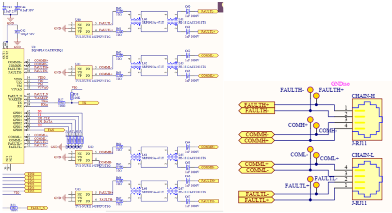
  • The problem is that the chip's communication pin is damaged.
  • There are two phenomena depending on the extent of the pin damage:One phenomenon is a complete loss of communication on one of the communication ports,Another phenomenon is that fewer chips in series can communicate, but more chips in series can't.
  • In all of these damaged chips, we measured the communication pin-to-ground resistance to be smaller than normal.

  • Hi user,

    Can you comment on what your subjecting the device to during the communication issue? Or is this happening upon power up? There potentially could be an issue with hardware pcb, testing or esd handling of devices that could be the cause. Do you also have any TI field contact or business email you can provide?

    Regards,

    Taylor

  • Hi Taylor,

    Chip damage during normal operation of the device,in the meantime,no power up, no personnel to operate;

    There's a little information you might need,Before that, we tested the insulation between the battery pack(PCB is inside of the pack) to the earth ground with an insulated instrument in hand.

    After the test,we power up the device,a small percentage of the chips were damaged, mostly during normal operation afterwards.

    Does chip damage have anything to do with this test?

    Other information notes:

    1. Our PCB is based on the official TI scheme;

    2. Our communication interface is equipped with ESD protection component.

    Regards,

    jun

  • Hi Jun,

    I am not sure of details of the insulation test but it could potentially be the problem, can you test ICs without the insulated test and see if there is damage? And please clarify how insulation test works, does it inject noise/esd?

    Taylor

  • Hi Taylor

    We've confirmed that the problem is not caused by insulation test.

    We tested and found that pulse voltage at the communication port when plugging in or out cables. Higher series pack voltage results in higher pulse voltage(PCB in the series battery pack), 300V will damage the IC, 150V won't.

    Did you run any tests about it? Are there other customers experiencing the same problem?

    How to protect the communication port?

    Whether isolated communications are necessary,What's the way to isolate the communication port of the BQ76PL455A-Q1?

    look forward to your response.

    Jun

  • Hi Jun,

    Please provide a diagram of your setup, board schematic and description of the pulse test you are doing so we can better understand your setup. Also, can you please answer the questions below:

    • "We tested and found that pulse voltage at the communication port when plugging in or out cables" ->
      • When plugging in or out which cables?
      • Are you injecting a pulse on the COMML/H communication pins?
    • "Higher series pack voltage results in higher pulse voltage(PCB in the series battery pack), 300V will damage the IC, 150V won't" ->
      • How many BQ76PL455 devices do you have in the stack?
      • What is the voltage that each individual BQ76PL455 sees (from TOP pin to GND pin)? The abs max voltage of this device is 88V so please make sure you are not exceeding this

    Best regards,

    Leslie

  • Hi Leslie,

    Our schematic:


    Test description:

    Test tool

    oscilloscope

    Test number

    2 BQ76PL455 devices in the stack

    Test method

    Measure the waveform on the pin with an oscilloscope when plugging or unplugging the communication cables

    Test pins

    COMML+/-, COMMH+/-, FAULTL+/-, FAULT H+/-

    Test result:


    Actual project usage:

    Voltage of individual BQ76PL455

    57.6V max (3.6V*16cells)

    Number of BQ76PL455 devices in the stack

    14 max


    other descriptions:

    1. Use a multimeter to measure the resistance of the communication(COMML/H) pin to the ground, the damaged chip pins are much less resistant than normal;
    2. If the number of BQ76PL455 devices in the stack more than 6, we plugging or unplugging the communication(COMML/H) cables, will damage the BQ76PL455, if the number of BQ76PL455 devices in the stack less than 4, will be harmless to the IC;
    3. The damaged chip is usually the one at the top or bottom.


    My doubts:

    1. Is it safe to communicate in a capacitive isolation mode?
    2. What other means of isolated communication are available for BQ76PL455?

    Best regards,

    Jun

  • Hi Jun,

    Thanks for the details. To answer your questions about isolation on the communication lines and to make sure you are following our recommendations, please review section 13 "Stack Daisy-Chain Configuration" section of the BQ76PL455A-Q1 Design recommendations document: https://www.ti.com/lit/pdf/slua791?keyMatch=BQ76PL455A-Q1&tisearch=Search-EN-everything

    Section 17.1 has circuit recommendation for a good Hotplug performance of the device. Please review this as well and follow the recommendations including TVS diode on COMM lines. 

    Best regards,

    Leslie