This thread has been locked.

If you have a related question, please click the "Ask a related question" button in the top right corner. The newly created question will be automatically linked to this question.

LM61460: Question about choosing inductor value refer to LM61460's datasheet.

Part Number: LM61460

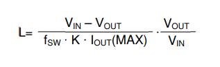
Normally, I learned choosing right Buck converter's inductor value is based on the below equation.


This is also in the LM61460's datasheet page 31.


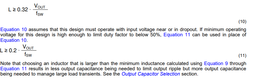
But page 32, there are two more equations about choosing inductor value.

So, I am confused.

In my system

Vin : 24V 

Vout : 19V

fsw : 1.18Mhz(from the webench tool)

k = 0.3

Iout(max) = 6A

If I calculate with first equation then L value is about 1.86uH.

If I calculate with equation 10. L > 0.32*Vout/fsw, then L value is about  5.25uH

If I calculate with equation 11. L > 0.2*Vout/fsw, then L value is about 3.22uH.

Refer to the datasheet, 

" Equation 10 assumes that this design must operate with input voltage near or in dropout. If minimum operating voltage for this design is high enough to limit duty factor to below 50%, Equation 11 can be used in place of Equation 10."

But, I cannot understand what this mean. My system's Vin is 24V, Vout is 19V. So is this input voltage near the operation?

Please, guide me for this. 

If I choose inductor value for 5uH, then this becomes same results as I assume that K(inductor ripple) for the 10%. I think this is very tight. 

What is appropriate L value for this system? 

  • HI 

    for equation 10, it is major choose a proper size of induct or work at a normal statues , choose K=0.3-0.6 can balance the winding loss , core loss and inductor size, so it is used for general buck converter inductor design.

    for equation 10, 11,  it is for meet dcdc system stability cause for LM61460 , Peak current mode implemented. and the slope compensation is internal. the subharmonic oscillation happens when the duty higher than 50% like your case, so when D>0.5, for avoid subharmonic oscillation, the inductor value should meet equation 10.

    for ripple no less than 10% rated current , it also consider the dcdc stability , small ripple will make the loop similar like voltage mode, so system need more capacitor to make the loop stable . 

    if duty is less than 0.5, it give you K limitation in this condition, if we choose D=0.4, the max K is 0.5. 

    In you case, you are working at high duty condition, you can choose 5uH inductor value, ripple is around 11% which can fit both.

    Thanks