This thread has been locked.

If you have a related question, please click the "Ask a related question" button in the top right corner. The newly created question will be automatically linked to this question.

UCC27714: Bootstrapped High side fets not switching

Part Number: UCC27714

Hi

I have the low side fets switching fine, but the high side ones are not doing much, below is this portion of the schematics:

Mosfets are FDP61N20

U8 is the UCC27714

U9 is isolation ISO7730FDWR

D26 is standard diode VS-3EMU06-M3/5AT

Other diodes are shottky DSS120UTR

Please can you let me know if you find anything wrong?

Thanks

  • Hello,

    Thanks for your interest in our driver. 

    From the schematic and gate components selection, I have few comments: The MOSFETs parallel connections have an equivalent load of 160nC load seen by the driver which translates to roughly 12.8nF gate capacitance. The equivalent recommended bootstrap capacitor should be sized such that Cboot >= 10*Cgate, for your case,  you have 220nF. In practice, you might need to need to double this capacitance to ensure HO voltage does not drop below HB-HS UVLO.

    Can you please share your current waveforms describing the issue.

    Then to debug, please turn-off power train and capture the following waveforms of HI, HB_HS (using differential probe), HO-HS (using differential probe) and HS_GND signals captured close to the driver IC pins.

    Regards,

    -Mamadou


  • Hello Mamadou

    Thank you very much for your reply.

    There are two caveats, the first is that I only have probe access to one driver, the other two unfortunatly are hidden underneath a controller PCB that I cant access. The second is I unfortuantly do not have a differential probe, but hopefully we can find a way around this.

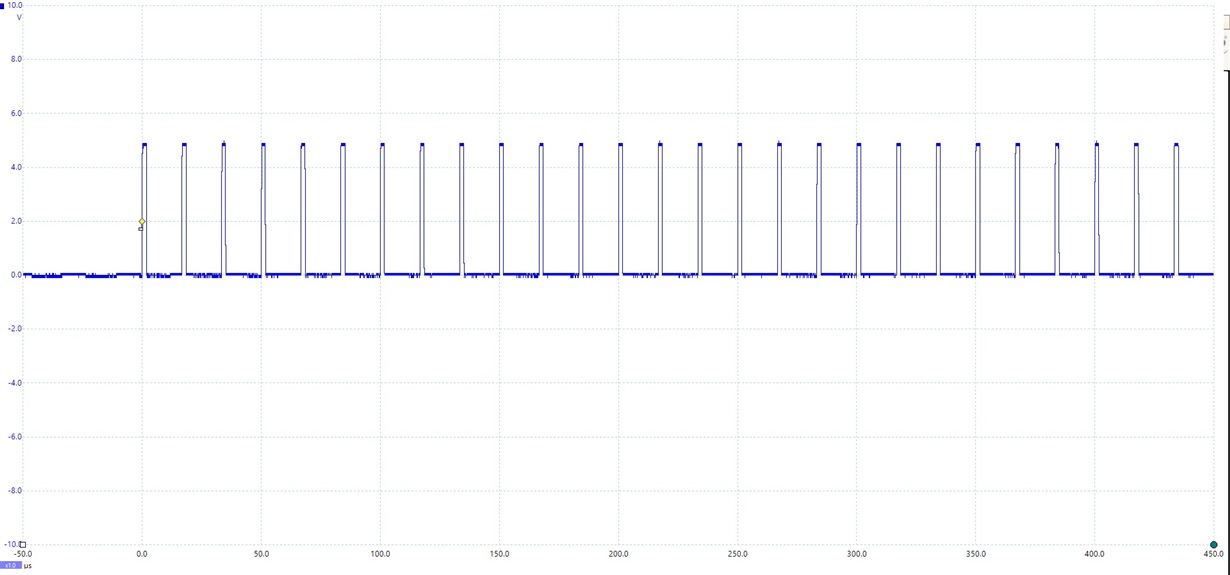
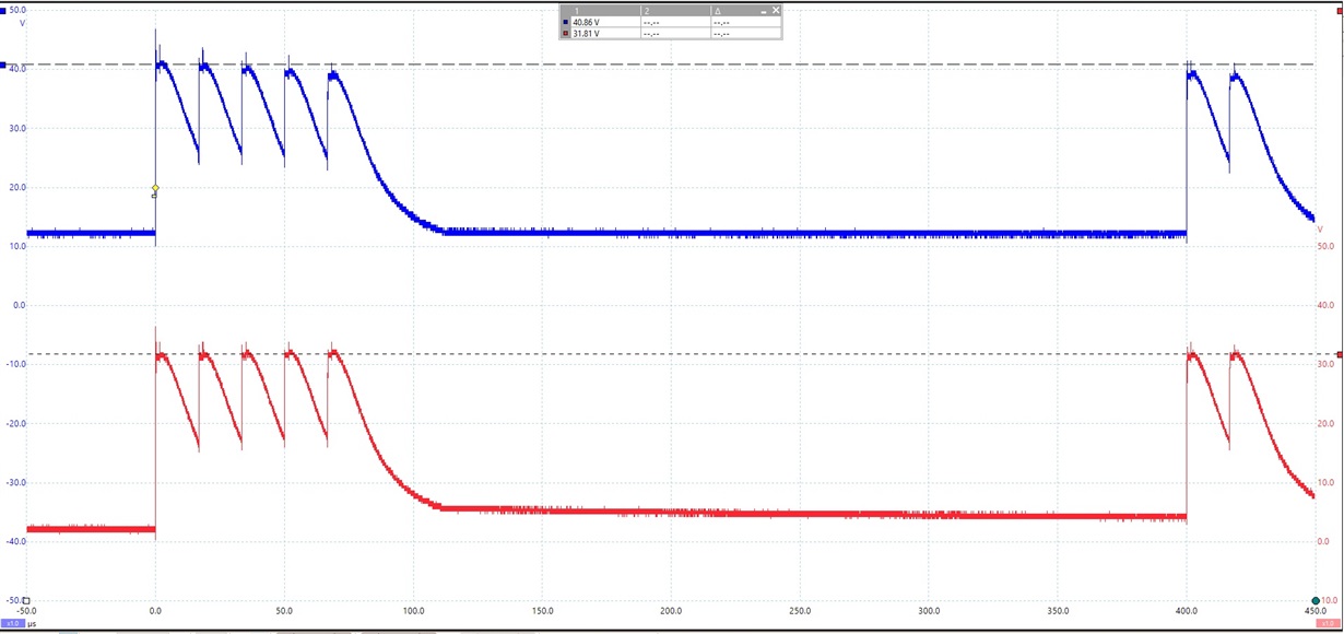
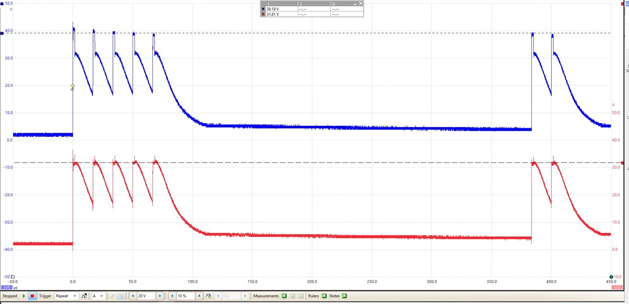
    I have disabled the output of driver C (the one I have access to. Here are the waveforms with respect to the regular GND (not isolated). The HS is connected directly to GND (non isolated) via  2K8 resistor (to bypass low side driver and to limit current to prevent damage). I have the High side PWM running @ 60Khz turning on /off every 10ms.

    I am also guessing you mean turn-on the power train with the EN? With the EN low, HB = 12.3V (steady), HS = 2.05V (steady), HO = 2.05V (Steady) with with respect to GND (not isolated)

    I have not increased the bootstrap capacitor yet, however is my Cboot not already 10x gate capacitance (Closer to 17x?)

    HI

    HB (Blue) and HS (RED)

    HO (Blue) and HS (Red)

    Please let me know if you need more information

  • Hello,

    I work with Mamadou supporting half bridge drivers, and I have some comments and suggestions.

    It looks like the voltage level of the HO-HS output is declining during the output pulses and the HB-HS bias is declining. I see that there are 3 10 resistors on each gate to source which is ~3.3K there will be current from these Vgs resistors discharging the HB bias. I would suggest increasing these resistor values by at least 3x which will result in ~10K total which is more typical of a Vgs pull down resistance.

    Since the operation has 10ms off times between pulses the frequency the driver has to operate and maintain high side bias is based on the 10ms or 100Hz.

    To determine the boot capacitance, use the equation from the UCC27712 datasheet application example below.

    Qtotal=Qg + IQBS/fsw, =174nC + 350uA/100Hz=3.67uC. This is much higher than just the MOSFEt gate charge.

    Cboot=Qtotal/deltaV. If you can tolerate 2V HB drop the Cboot will be 1.8uF. or 2.2uF is a standard value.

    It is not clear that the HS voltage is going close to ground during switching. The HB bias capacitor is charged from VDD when the HS voltage switches to ground which usually happens when the low side MOSFEt turns on. Is the low side FET gate drive active during the operation shown? If HS does not switch close to ground, there will be an issue maintaining the HB bias regardless of increasing the HB-HS capacitance.

    Can you try the suggestions of increasing gate to source resistance on the high side FET’s and increasing the HB-HS capacitance?

    Regards,

  • Thannk you Richard

    I have replaced the bootstrap cap and mounted a 2.2uF for Phase C, I also repladed the 10K gate source resistors with 51K's (it was the closes I have in stock to 30K).

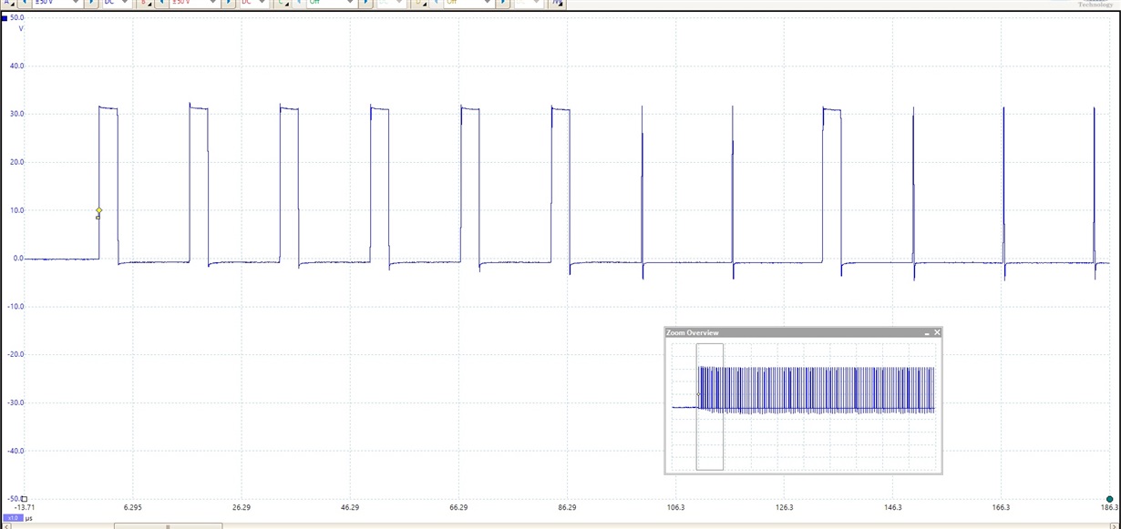
    The results were better, but the issue was not resolved. However, as I am testing just the high side circut in isloation (Via a 2K8 resistor directly between HS and GND) I thought I might test it with a smaller resistance. I went down to a 220R and the waveform looked much better but again not ideal. I then attached one phase of the BLDC motor to HS and another to GND then started playing around with the duty cycle. As the duty cycle increased I started getting some misfires (see scope below). When I then tested high side Phase A the same way (but still with the 0.22uF and 10K gate source resistors) the issue was not there.

    Is the issue below a simple one fo fix, or should I stay with the components that seem to work better (for now at least, I only went up to 5A on the PSU).

    Thanks

  • Hello, Thanks very much for the patience, Richard will get back to you On Monday

  • Hello,

    Thank you for the update, it does sound like there is improvement when you are actually switching the power train. I think the issue with your 1st setup, using resistance to pull down the switch node and switching the high side, is that there is not an adequate current path the charge the HB-HS capacitance in a short time.

    When you are switching the power train, when you turn on the low side FET(s), this provides the path the charge the HB capacitor relatively quickly. It could be that with the HB capacitance I suggested that could support the 10ms burst rate, the HB capacitor is not able to be charged fast enough during the low side FET on times.

    I would continue with the component values that are working well now, It may be that during the switching off times (10ms) that there is a path to keep the HB capacitor charged, which I am not aware based on the information given so far.

    Regards,