A related question is a question created from another question. When the related question is created, it will be automatically linked to the original question.
If you have a related question, please click the "Ask a related question" button in the top right corner. The newly created question will be automatically linked to this question.
TPS92641: when using the shunt FET dimming, the output is unstable
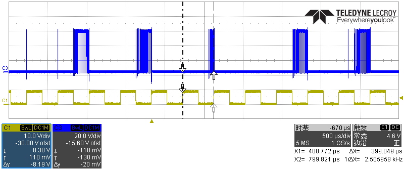
The chip has to go into low duty cycle/frequency when shunt fet dimming because the off time voltage is near zero since this is a synchronous part (the voltage across the Shunt FET when it is on and the lower TPS92641 voltage drop). This means it turns on for a minimum on time at low frequency. So the chip is working when the shunt FET is on, that is the narrow pulse every so often.
There are a few things going on. On of them is the output capacitance. Try removing C141, C142, C145, C146. This part regulates valley current. The compensation before going into shunt FET mode is set for Vled, once shunted the ripple current drops. This sets the regulation point higher so when it turns back on comp needs to charge to start up again. Also, that output capacitance becomes switching loss for the Shunt MOSFET.
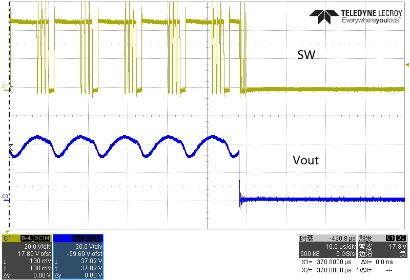
In your scope picture you can see the duty cycle increasing when the shunt fet turns off, this is due to your output capacitors charging.
There is also a section in the datasheet about zero current, you are near that, look at implementing that though it only helps some. See section 7.3.4.
You also have a very low Viadj voltage, you may want to try a higher current sense resistor value so the Viadj is not so low.
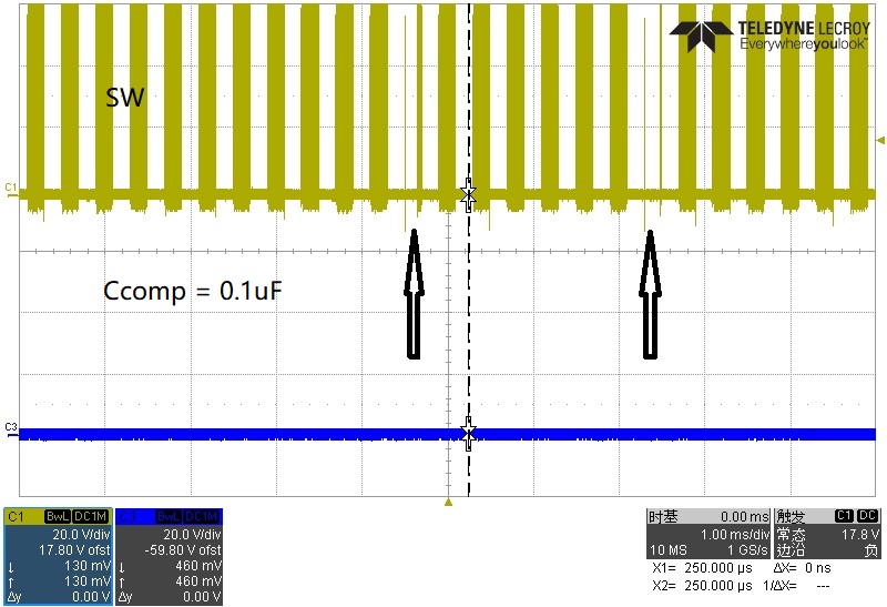
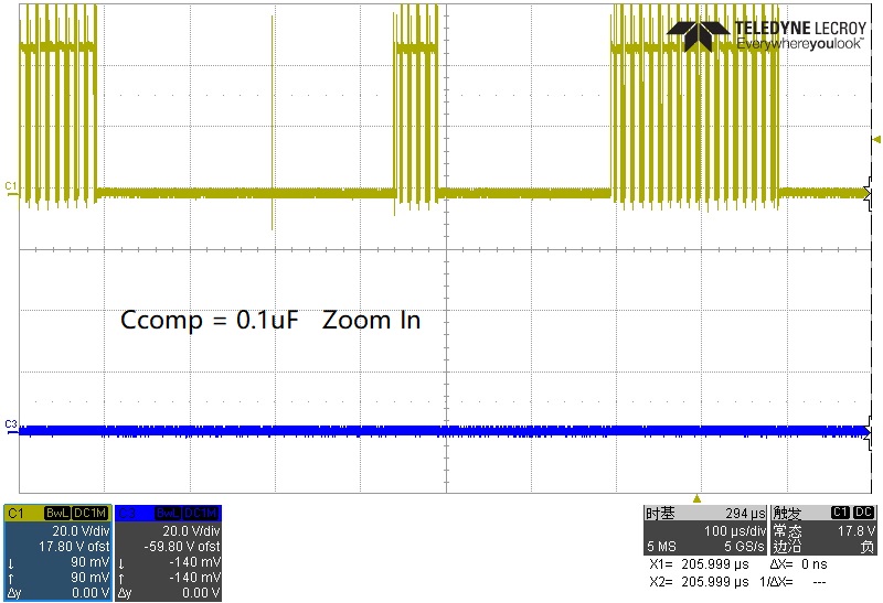
I removed the C141, C142, C145, leave the C146, so the Cout is 0.1uF now. The Viadj is now increased to 1V. And a Roff of 750K is added to the circuit.
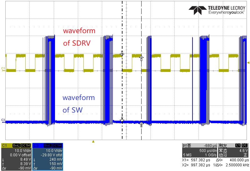
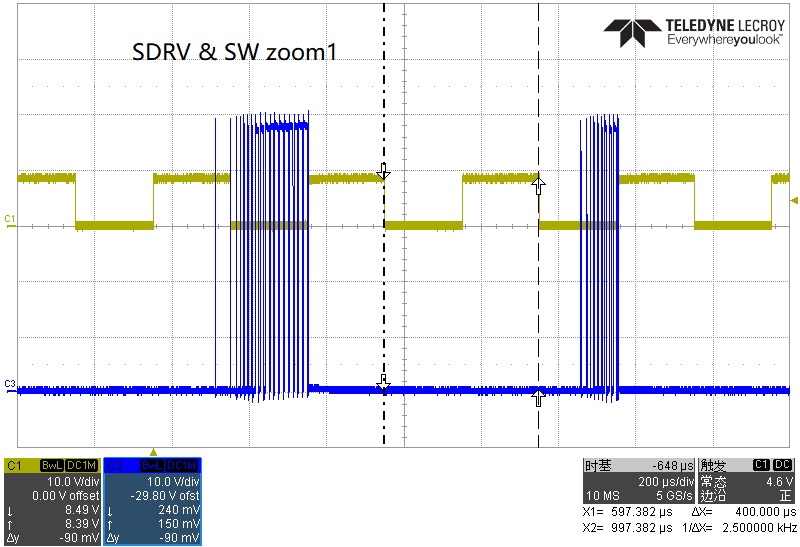
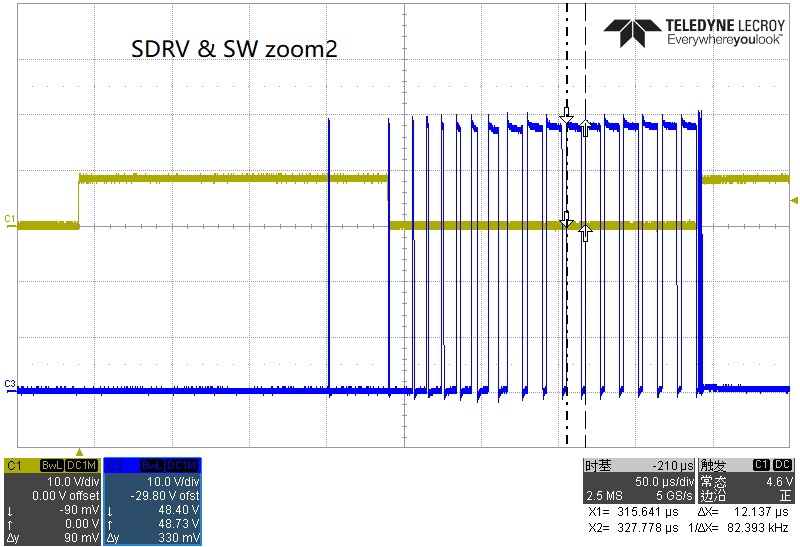
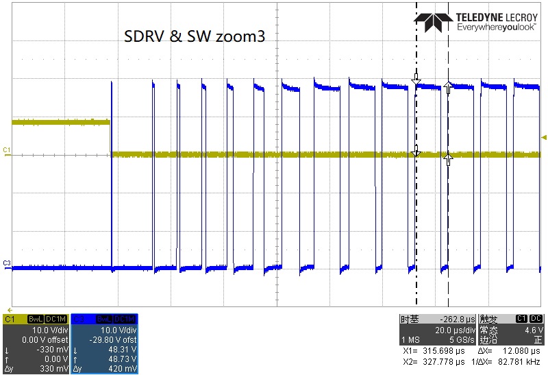
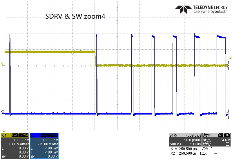
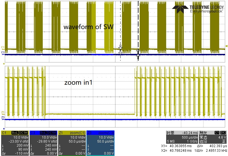
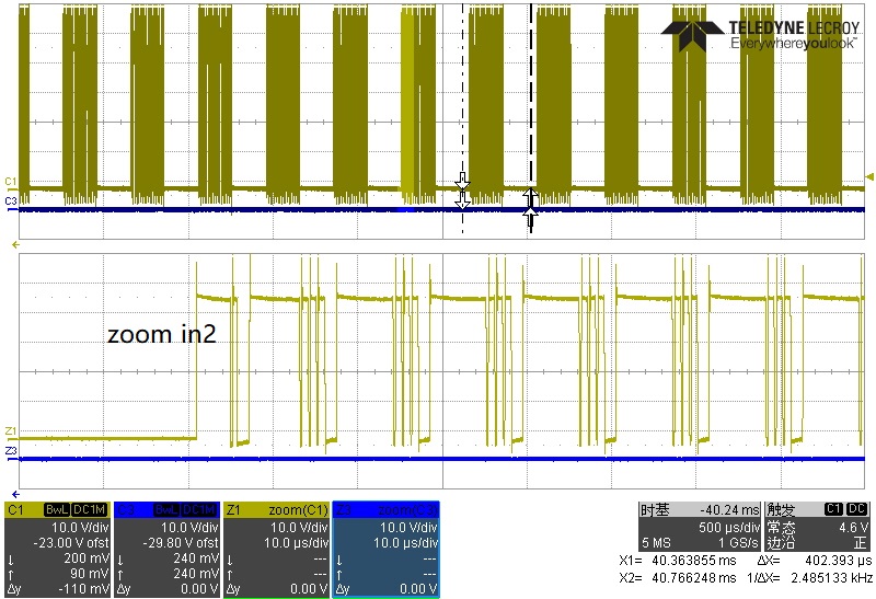
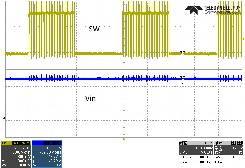
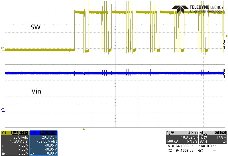
After all of these, the SW waveform is like this:
The lower waveform is the zoom in of the upper part.
According to the waveform, the frequency of the SW is the same as the SDRV now, but the narrow pulse still can't be seen when the shunt FET is on; When the shunt FET is off, the waveform is more strange now, and the temperature of the High Side MOSFET Q13 raised quickly.
What is your load? How is it connected? Is there anything such as filtering between the driver and the load?
Try changing R145 to 165 Kohm or so from 137 Kohm, you may be hitting OVP.
You may need to add a little more output capacitance, 0.22 uF or 0.47 uF, your switching frequency is just above 100 KHz so your inductor current ripple is 1.33 Apkpk with a 47 uH. This means there is a portion of the current ripple that is negative current at the output. below 665 mA.
The load is a string of LEDS, which the number is 12, Vf = 3V, and the load is directly connected to the CON17, there is nothing between the driver and the load.
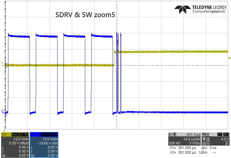
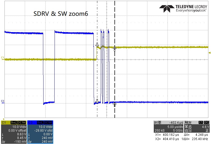
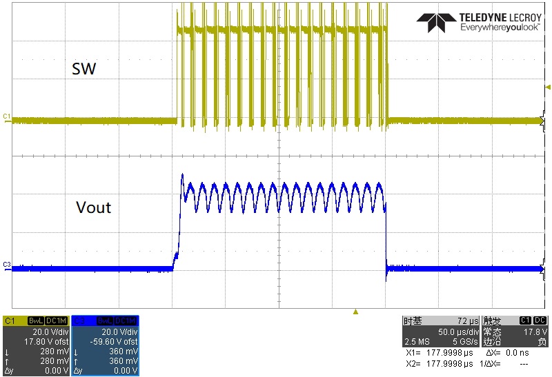
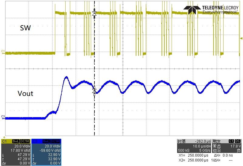
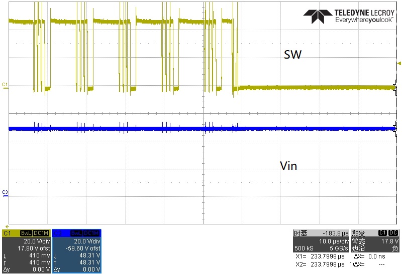
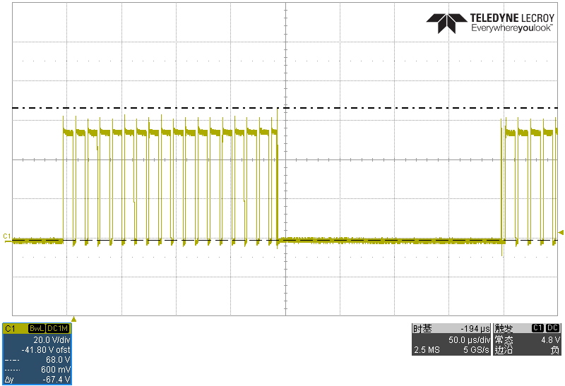
I changed the R145 to 180K, the waveform when the shunt FET is off seems right now, but there is still no pulse when the shunt FET is on.
That is fine. The only time there should be an off pulse is if the current dropped. Being shunted it does not drop fast. The issue would show up looking at the output current with a current probe right when the Shunt FET turned off. Check if the current is low. This won't be the case since you are running at such low current and the ripple is fairly high.
Your output is getting above 42V and was hitting OVP. Changing R145 moved OVP higher. It also affects the switching frequency a little so you may want to check if it is where you want.