This thread has been locked.

If you have a related question, please click the "Ask a related question" button in the top right corner. The newly created question will be automatically linked to this question.

UCC28950: Dahasheet explanation UCC28950

Part Number: UCC28950

Hello

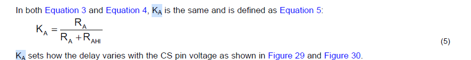
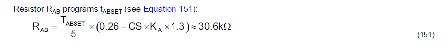
1.Datasheet contains a Chapter “Application and Implementation”. This chapter is an example of calculation of converter with numerical data for this particular converter. Formulas 151 and 154 in this chapter use parameters CS and KA, but I could not find any numerical value for these parameters, calculated or set before it have been used in these formulas.

2. There is a circuit diagram on page 1 of datasheet. On this diagram dividers RAHI&RA and RAEFHI&RAEF are connected to CS pin of controller. But on page 38 (Figure 48) these dividers are connected to VREF pin. At the same time, on page 20 it says that this divider connected to CS(“RA and RAHI define the portion of voltage at pin CS applied to the pin ADEL (See Figure 48)”) . On page 55 these dividers are connected to CS. On page 62 these dividers are connected to VREF but also can be connected to CS. Note that in your Excel calculation tool (SLUC222D) these dividers are connected to VREF. I could not find any explanation for this.

  • Hi Lev

    A1/ KA is defined in Eq 5

    CS in these equations is the the peak voltage at the CS pin.

    A2/ The ADEL and ADELEF pins are used to modify the baseline delays set by the resistors at the DELxx pins. If ADEL and ADELEF are connected through a potential divider to the CS signal then the delays are modified adaptively - that is they become a function of the signal at the CS pin.

    However, it is also possible to use the ADEL and ADELEF pins to apply a fixed modification to the baseline delays by tying them to a fixed voltage - usually derived via a potential divider from VREF.

    Both approaches are valid - it depends on which suits the designer best: The design example in the DS and the Excel calculator uses the second approach, the application diagram on P1 uses the first.

    Here's a document that gives more details.

    /cfs-file/__key/communityserver-discussions-components-files/196/3007.Calculating-Adaptive-Delays.pdf

    Regards

    Colin