This thread has been locked.

If you have a related question, please click the "Ask a related question" button in the top right corner. The newly created question will be automatically linked to this question.

TPS22810: Question about QOD Fall time design requirements in TPS22810's datasheet

Part Number: TPS22810

Hello, I am going to use TPS22810 for load switch.

After reading datasheet, I don't understand something.

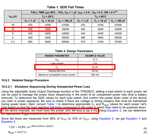
Table1. is datasheet's QOD fall time table.

and below, there says " In the above example we must have this power rail's fall time to be 4ms. 

Refer to table, if fall time to be 4ms with Vin 12V, then CL 's value would be about 10uF. (10uF for 4500us = 4.5ms)

But in the datasheet, they choosed CL for 22uF.

Then I think this will make fall time about 10ms.

Am I understanding something wrong?

And in addition,

what is normally people use value for desired fall time and max inrush current?

Are there any some kind of rule of thumb like that fall time and max inrush current based on load current or any parameter?

(For example, normally when choosing buck's inductor ripple current as 30%. )

Thanks.

  • Hi Seokmin,

    Welcome to E2E!

    Thank you for pointing this out! That is actually a typo in the document. As you may notice in Table 4 the desired fall time is 20ms, and in equation 4 they also use 20ms.

    Something to keep in mind is that the fall time does not only depend on the value of the output capacitor. As you may notice the CL = 22uF capacitor for a fall time of 20ms also doesn't make much sense when compared to Table 1. This is due to Table 1 being comprised of the fall times with QOD shorted directly to VOUT, meaning they are only discharging the capacitor though the internal resistor. Adding an external resistor will change the fall time by increasing the pull down resistance. The purpose of the example in section 10.5 is to showcase how to change the fall time with the use of an external resistor.

    I can't think of a CL value normally used for a desired fall time or inrush current since different systems have different requirements. There are several parameters to consider when it comes to inrush current/fall time, and several way you can go about it.

    • Inrush current:
      • Equation 9: Start with your requirements and adjust the rest of the variables as needed. For example, several systems a have a required rise-time/slew-rate, and a required output capacitance for which you can check if the inrush current will exceed the abs max current spec of the device.
      • Equation 3: To get the desired slew rate needed for the inrush current choose a CT capacitor value. The equation is valid for CT>1nF.
    • Fall time:
      • Equation 1: This is the value of the QOD resistance. RQOD = RPD if no external resistance is used.
      • Equation 2: RC decay with the load capacitance and load resistance.

    Let me know if you have any questions!

    Best regards,

    Andy Robles