This thread has been locked.

If you have a related question, please click the "Ask a related question" button in the top right corner. The newly created question will be automatically linked to this question.

WEBENCH® Tools/UCC28742: ucc28742 have no Drv pulse output after Vdd reach 21.6V.

Part Number: UCC28742

Tool/software: WEBENCH® Design Tools

Hi TI

I'm using reference design from WEBENCH and build UCC28742  based DC-DC flyback converter. Because I very trust TI product quality, so I direct implement the diagram from WEBENCH but I found many issue now. 

1, I using blow diagram from WEBENCH design tools to get a flyback dc dc converter with specification 30-150Vdc input and 3.3v 1A output. After supply 30V to the circuit, the circuit no response, no PWM Signal from drv and no voltage present at output. I did replace new ucc28742, issue remain, so I check on UCC28742 Datasheet and did changes according datasheet sample diagram. You may see red colored wires was placed to connect Dvdd to Cvdd for continues supply after start up. 

2. After done the changes, i replace new UCC28742, and monitor of Cvdd, voltage able to reach 22V but DRV pin still remain no pulse output. I power up and down several times to try get at least one pulse but answer is no. And due to no driving signal, so the CS, VS pin voltage at ground 0 level. Replace new ic reamin same issue. No signal output from Drv pin. 

3, i searched TI support, I try to remove mosfet M1 and replace new UCC28742 and check on the DRV, still no signal. 22V present at Vdd. GND connection also checked ok. 

4. My PCB only differences was changed value of Rt1, Rt2,Rt3 to 2.37Mohm for faster startup and M1 using IRFU220NPBF, Transformer follow design 29Turn, 

I would like to get support from TI. Hope can get the answer soonest.  

  • Hello,

    I will move this to the Webench forum so they can look into resolving this issue with the schematic.  Sorry for the inconvenience.

  • Hi Mike

    Thank you for your supporting. Today I made a new testing again with everything refresh, monitor voltage Vdd and DRV signal from oscilloscope, I observed when voltage just above 21.6 at Vdd pin, DRV has no output. When I rise the voltage level to around 23v at Vdd pin, the voltage will drop to around 10v and then charge up to 23v again and repeated.  I also searched online found another user was also facing exactly same issue and was not solved. Please, need your support. 

    My update: I try to using signle mode at oscilloscope, it randomly shows a three pulses after power on. But circuit still not working.  voltage still charge up and down at Vdd pin. This seems under fault protection mode after initial 3 pulses.

  • Hi ChuneLei/MIke,

    We will fix the schematic on WEBENCH. The fix will be available on ti.com by the second week of July. We will inform you once it is available.

    Thanks & Regards,

    Praveen

  • Hi Praveen.

    While waiting for the WEBENCH issue to be solved, do you have any advise on the issue i'm facing? Since I did changes on the error link, what other possible reasons will be the cause for DRV no output? I would like to get advise from you first and try to solve it soonest.  

  • Hi ChuneLei,

    I have forwarded your query to the concerned team. The team will get back to you soon.

    Thanks & Regards,
    Praveen

  • Hello,

    When the VDD pin is cycling  between VDDon and VDDoff most likely there is a fault conditions.

    When VDD first comes up the UCC28742 will give 3 sample pulses looking for a fault.  If a fault is observed the gate drive will shutdown and VDD will discharge to Vddoff.  The three major faults are.

    1. Over Current Protection
    2. Input Under Voltage
    3. Output Over Voltage

    The VS divider monitors input under voltage when the switch is on and output over voltage on the aux winding while voltage is being delivered to the secondary.

    Section 7 of the UCC28742 data sheet Equation 1 and 2 explain how to set the input under voltage/brown shut down and output OVP with the VS divider.

    It is also important not to have too much ringing in the aux winding to accidently trigger an OVP.  Page 14 in the data sheet goes into detail on how the aux signal would look.

    Other recommendations I can make is to use and RCD clamp on the switch node instead of TVS clamp.  It  helps dampen the ringing.

    You also might want leave place holder across the output rectifier just in case additional snubbing is needed.

    You should study the Aux, CS, VDD and VOUT during power it.  From these three signal you will be able to determine what fault is shutting down you power supply.

    Regards,

  • Hi, Mike

    Thank you for your detail explaining on the methods to solve the issue I'm facing, I will work on according your advise and update again once solved. Thank you

  • Hi All. 

    I did check on the following signals and it seems also not working. . . 

    Caculated Rs1, Rs2 value and changed also not working. . Mosfet was also removed and measure on the output signal. But not ok. 

    main supply voltage I try to rise up to 120v , no signal also. 

  • Hello,

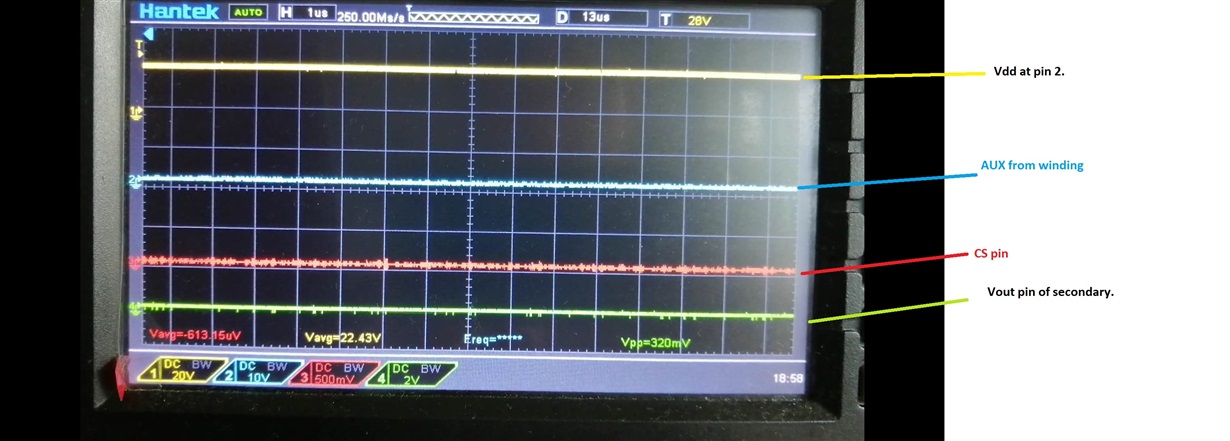
    Could you send oscilloscope plots of Aux, CS, VDD and VOUT during power it.  From these three signal you will be able to determine what fault is causing you not to startup.

    More than likely you are shutting down to an OVP caused by aux winding ringing.

    It appears that you are using a TVS clamp.  To dampen the ringing on the switch node you can do the following.

    1. Put a 1 nF capacitor and a 511 k ohm resistor in parallel with Dz.
    2. You could also add a snubber across D2 if you need to dampen the ringing further.

    Regards,

  • Hello Mike

    Thank you for your reply. Follow your instruction, I captured the oscilloscope wave shown below for your help to verify and to better understand I also attached photo of my PCB currently using. Some wire jumps due to diagram error. 

    The wave didn't change at all.  https://youtu.be/krVsl0vSYjM

  • Hi Mike

    While waiting for reply, I build the last pieces of PCB to test out ucc28742 and result is same, no drv output. Components was purchased from TI store and hopefully no issue. Important is the IC no able produce pulse output, even the first three pulses also random event. I taken a video and link shown below. Hope you can find something abnormal. Will also try to adding 1nF cap and 511k resistors after this. 

    https://youtu.be/krVsl0vSYjM