A related question is a question created from another question. When the related question is created, it will be automatically linked to the original question.
If you have a related question, please click the "Ask a related question" button in the top right corner. The newly created question will be automatically linked to this question.
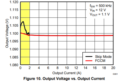
We want to check why the load regulation curve is like this.0-2A, the load regulation change a lot, but it keep stable after the current above 2A. (Even the FCCM mode)Thanks.
Because the TPS53353 uses D-CAP mode control with valley voltage regulation, as the inductor current becomes negative during the high-side FET "OFF" time the relationship between the internal ON time and the external SW voltage on-time changes as the negative inductor current drives the SW voltage high during the dead-time, the peak to peak ripple increases at light load, even in FCCM so we see a small rise in the output voltage as part crosses the critical conduction boundry.
This is much more pronounced in Auto-skip mode as more and more of the inductor ripple current is greater than the average load current.