This thread has been locked.

If you have a related question, please click the "Ask a related question" button in the top right corner. The newly created question will be automatically linked to this question.

LMZM33606: Connection of AGND in layout

Part Number: LMZM33606

Hello,

I have huge design in which I'm not able to create a separate AGND on PCB. So is it ok that the components connected to AGND are only connected to the ground through the IC? Also is there a real reason for separating these two? My understanding is that nowadays its not recommended to separate grounds but instead to have one solid ground layer.

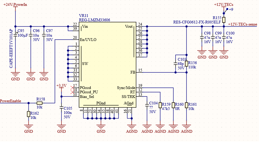
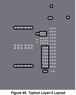
Also I would like to know is there some reason to have these power islands on the ground layer as I don't see any sense in them and ground layer usually shouldn't have any gaps?

Best regards,

Petteri

  • Hello Petteri,

    I do not believe it splitting power planes should ever be done.

    The buck or any smps is often viewed as the noise source in most applications and as a result, mitigation of noise should be paramount for that of the buck.

    Continuous ground layer underneath the IC can allow for low inductance return path, in addition, to shielding properties and improved thermal performance.

  • Hi Marshall,

    Thank you for the quick reply!

    I think so too. Ground plane should always be continuous and not splitted. Though, with this component the datasheet is so strongly suggesting otherwise that I'm a bit unsure if there is some special case with it.

    So do you think that the datasheet is giving wrong advice by saying that PGND and AGND should be kept separate? Can I ditch the AGND and just use one ground for both?

    Here is a screenshot from the datasheet:

    Best regards,

    Petteri

  • Hi Petteri,

    AGND and PGND are internally connected to one another in the module so both nodes act as the same return path. However in PCB design, the AGND and PGND are separated because the AGND is a ground return dedicated to components that are sensitive to noise such as RT and FB. The idea here is that current that flows through these sensitive components should reach AGND before reaching PGND. PGND is generally polluted with noise coming from the input supply so having an immediate decoupled analog ground (AGND) would further help with noise immunity.

    As such it is only recommended to have an isolate island of AGND copper plane big enough to get these sensitive components to the return path. The entire board should have a large PGND copper pour, as Marshall mentioned, for thermals and shield purposes. If you split your PCB's PGND through the middle, then you will only have half the board for thermal relief. 

    Notice how the isolated AGND copper plane on Figure 48 is only a fraction of PGND and is only on the Top Layer while PGND is the large majority of the ground pours on all 4 layers. If this can not be accommodated for, you can simply connect to PGND and have a less noise immune design that still operationally works. 

    Regards,

    Jimmy 

  • Hello Jimmy,

    Thank you. Though, the part that I'm mostly confused about is Figure 51. because the bottom layer is filled with AGND and I have no idea where else I would connect that AGND pour.. Also it looks bad to me regarding thermals as I've understood that most of the heat is coming from PGND pads.

    Anyway I guess the best option for me is to have a AGND island on top and just forget the Figure 51. (bottom layer) and fill the bottom with PGND instead of AGND. Please, tell me if I'm wrong :)

    Best regards,

    Petteri

  • Hi Petteri,

    I see what you mean now. Figure 51 is an entire layer of AGND. Honestly I would have created that layer as PGND and have the RT via to the AGND copper pour. The more PGND you have, the better the thermal design will be. Also note that having a small copper island under the SW pins also act as thermal relief.

    You can design your board for your needs and fill the bottom with PGND instead of AGND. This should not significantly impact the performance of your design.

    Regards,

    Jimmy