This thread has been locked.

If you have a related question, please click the "Ask a related question" button in the top right corner. The newly created question will be automatically linked to this question.

TPS543B20: Feedback resistor

Part Number: TPS543B20

Hi,

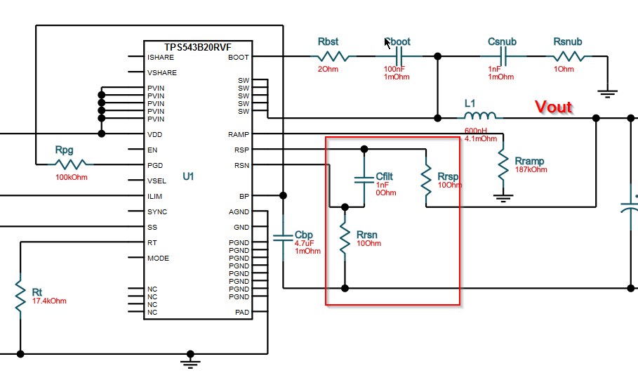
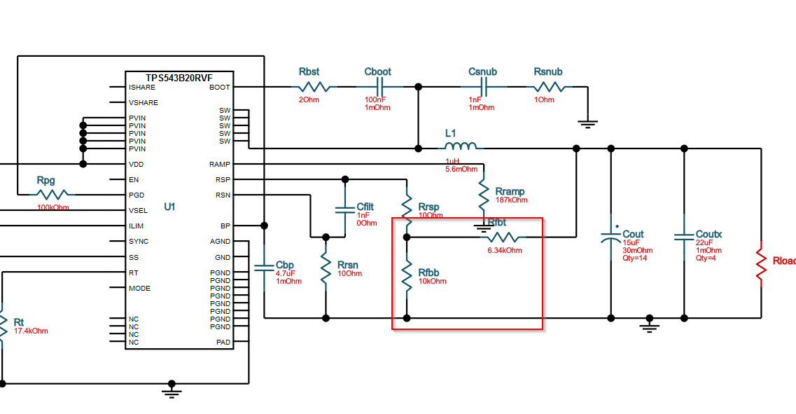
I'm using TPS543B20. In the section "8.4.16 RSP/RSN Remote Sense Function", I have two questions.

1. How to calculate the values of the feedback resistors on the RSP and RSN?

2. When to use feedback resistors or when not to use feedback resistors?

Thanks.

Kevin Xiong

  • Hi Kevin,

    First let me answer 2) - feedback resistors are required if your intended output voltage is not equal to one of the fixed voltage reference options denoted in the Electrical Characteristics p.8. The same reference options are also listed in Table 2. If your intended output is one of the reference options, you can tie your output directly to RSP and gnd to RSN to have very good output accuracy by using the corresponding reference option for your output with the VSEL pin resistor.

    However, if you are taking your feedback from a remote load, we often recommend including optional placeholders for an RC filter as shown in the below WEBENCH design schematic to help filter out any high frequency noise. The cutoff frequency of this filter should be placed at the switching frequency (fsw) at the lowest. Making the cutoff too low will introduce phase lag into the feedback loop at the loop crossover frequency (typically around fsw/10) and impact stability.

    1) Assuming the intended output voltage is higher than the available voltage references, then you will need to add a feedback resistor network. The output voltage can be calculated as Vout = Vref * (1 + Rfbt/Rfbb). A common value used for Rfbb is 10kohm, then from there Rfbt = Rfbb * (Vout/Vref - 1) by solving the Vout equation. See below WEBENCH design schematic for 1.8Vout and 1.1V reference.

    When using an output resistor divider with a low-pass RC filter a shown above, you should consider the effective R as Rrsp+(Rfbt||Rfbb) when setting the filter cutoff frequency. Again, the low-pass RC is optional, but putting placeholder slots on your board is recommended in case you later find the need to add filtering during your system testing.

    Regards,
    Kris