Hi All,
My customer is designing an isolated power supply independently from battery for a forklift application.
I was asked to find a demoboard with below specs for the power part:
- Vin Min <= 24V; V max >= 79 V (DC)
- VinNom 48V
- Vout= 12V, isolated
- Absorbs the minimum current possible with no load even though enabled (Low Power)
- IoutMax>=2A, Iout Nom 0,5A.
- No optocoupler
I was already in contact thru email with PDS team and they suggested me PMP9009, that's a good design but does not meet all above specs.
Apart from a custom design could you please support me for the below technical questions?
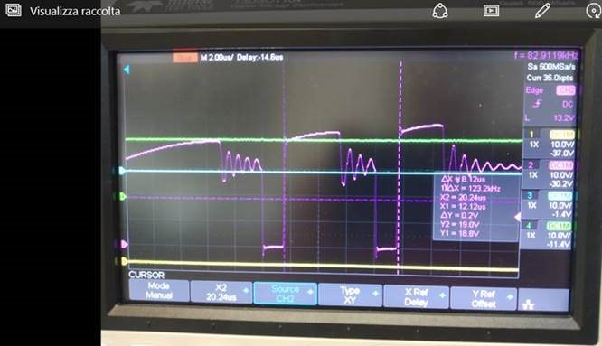
Customer while using the UCC28730 demo board found some problems not solved in the ds of UCC28730, which states that the controller imposes a maximum switching frequency of 83kHz instead from the measurements made by customer it emerges that at the start between the second and third commutation there is a period ranging from 10us to 6.4us against the 12us estimated.
This means that the diode at the secondary has a conduction time such that its duty cycle exceeds 0.432 (DMAGCC).
Customer also found out that this period of time changes by disconnecting the C6, which connects the masses between primary and secondary, and by shorting it or using it normally in none of the 3 cases the device starts.
Could you please help me in understanding this unexpected switching?
I am attaching the screenshot of what said above (screenshot1).
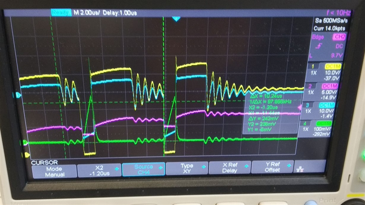
I also attach the images of the tests customer carried out on the component, with a brief description:
All tests were carried out with a supply voltage of 28 to 40V.
Description of the images
1- In the IMG ... WA0007 the voltage on the TP2 is shown in blue, feeding the ucc28730. And in purple the output voltage. It clearly shows that the device enters protection
2- In the VERDECS image ... It is shown with the green trace: CS TP5, Viola Vout +; Vaux blue; yellow Vdrain of q1.
3- In IMG ... WA00022 it is shown that the switching frequency exceeds 83kHz, also there was a slow diode which I replaced with a schotcky which will find the pN in the schematic.
4- In IMG ... WA00030 you can see how the oscillation is sinusoidal having changed the diode on the secondary.
5- In IMG… 095451 you will find a photo of the schematic the transformer used is 7491195212 with an L of 21uH and a turns ratio between Nps = 1.33 / 1 and npa = 1.33 / 0.89
The installed shunt has a value of 0.3 Ohm contrary to what is reported to prevent the secondary diode from exceeding the DMAGCC.
Any further comments?


