


Dear experts,
We are developing a 6S BMS based on bq40z80, for high currents up to 100A.
We have a few questions regarding the connection of VSS and PGND:
1) On the EVM, why is PGND used as a ground on the SMBus connector, instead of VSS, while the bq has VSS as a ground?
2) On the EVM, VSS and PGND seem to be connected this way:
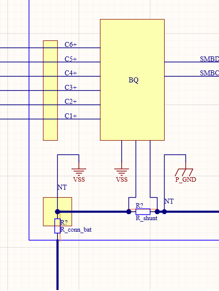
Is this diagram right?
This means VC1 reading relative to VSS will vary depending on battery current. Can the bq account for this voltage drop and compensate it?
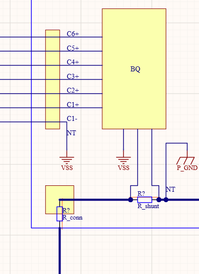
3) Why not running an additional balancing wire directly from cell 1 (-) terminal, like this:
Here is a diagram of the complete BMS:
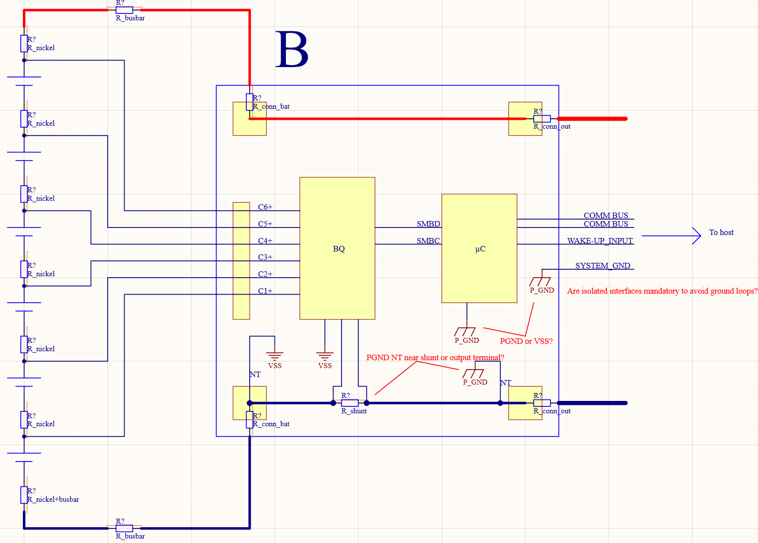
A few things to ask here:
4) Do we have to connect the PGND Net Tie near the shunt or near the BMS output connector (PACK-)?
5) Must other devices on the BMS, such as a µC, be connected to PGND or VSS, and why?
6) Must the host ground be connected to PGND or VSS through the BMS signal connector? Or no ground at all on this connector to avoid ground loops?
6) Do we need an isolated transceiver if using CAN bus to connect to our host through the µC?
7) If we run GPIOs between host and the BMS µC (such as here, "WAKE-UP_INPUT"), do we need to isolate these signals? As their reference ground may shift a bit (< 200 mV) because of high currents, and introduce noise (motor involved)
Last question:
8) On the battery pack (21700 cells), is it better to solder voltage sensing wires on C1+, C2+, C3°+... or on C2-, C3-, C4-...? Because voltage drop on the nickel strips, at high currents, can be as high as a few 10's mV
Thanks in advance!

