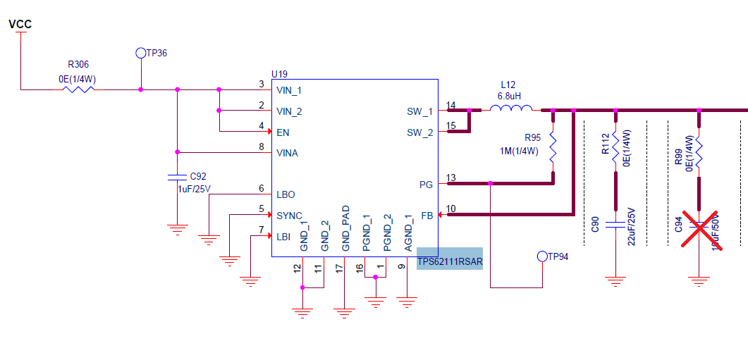
Ripple more than 40mVp-p @ 5Khz with 6mA load @ 3.3V.
as im using for the 4-20mA loop it should be less than 10mVp-p
please suggest some solution.
Ripple more than 40mVp-p @ 5Khz with 6mA load @ 3.3V.
as im using for the 4-20mA loop it should be less than 10mVp-p
please suggest some solution.