On our in house designed gate drive board, the FLT pin is low but I can't figure out why.
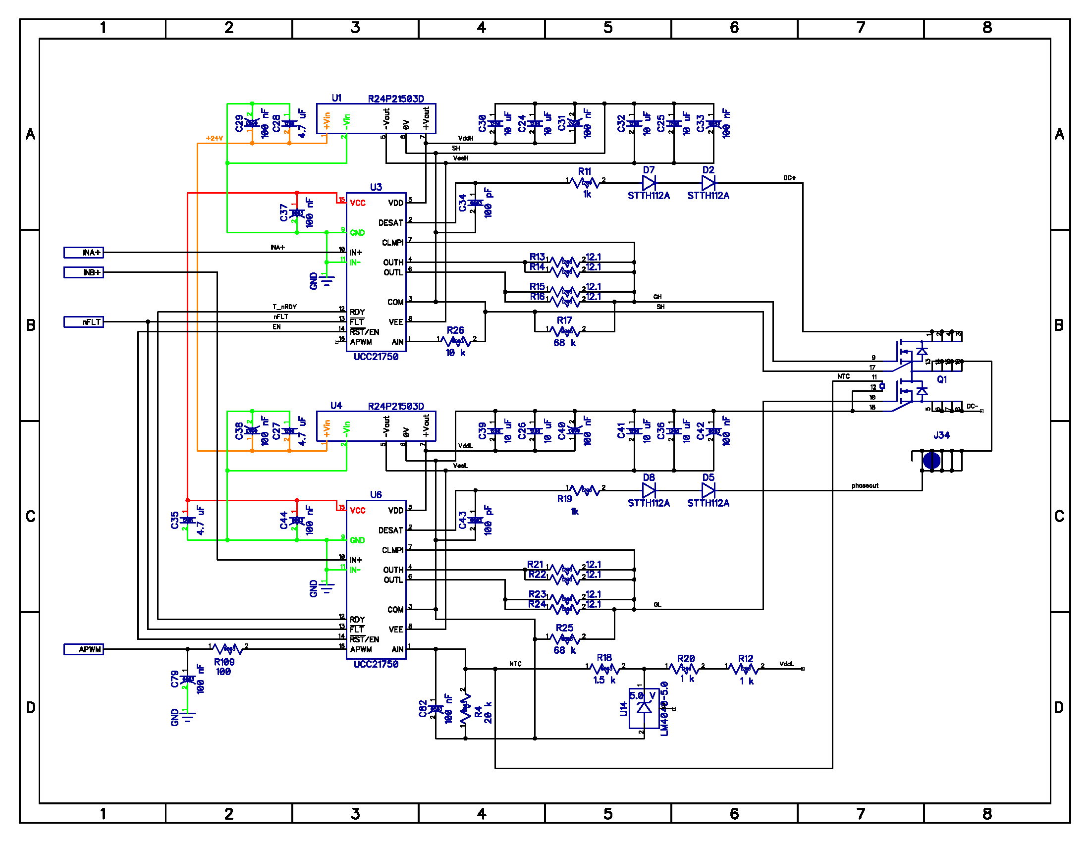
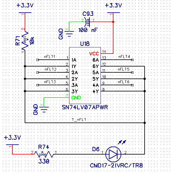
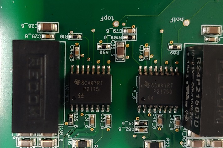
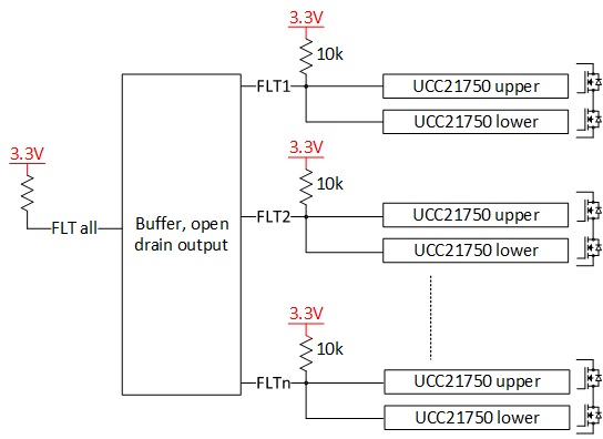
The basic configuration is below. There are multiple UCC21750 chips on the board; pairs of UCC21750s (for driving a half bridge) have their FLT pins tied together and pulled up with a 10k resistor. These FLT1-FLTn signals are then fed to a buffer where the FLT signals are ANDed into one single FLT_all signal.
On the board, FLT1 through FLTn are all low which indicates a FLT, but the DESAT pin is only 200mV. The other pins read as follows.
| UCC21750upper | UCC21750lower | |
| IN+, IN- | 0V | 0V |
| RDY | 3.3V |
3.3V |
| FLT | 0V | 0V |
| RST/EN | 3.3V | 3.3V |
| Vcc | 3.3V | 3.3V |
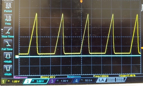
| APWM | 0-3.3V PWM with 60% duty | 0.5-2V PWM with 38% duty |
| Vee | -3V | -3V |
| CLMPI, OUTL, OUTH | -3V | -3V |
| Vdd | 15.8V | 15.8V |
| DESAT | 200mV | 200mV |
| AIN | 2V | 3V |
The UCC21750lower with the APWM & AIN at 38% & 3V, respectively, has an external circuit for the AIN pin that is designed to connect to the MOSFET NTC. The UCC21750upper simply has a 10k pulldown for AIN. This is why upper and lower AIN/APWM are different.
What could be causing the FLT to be pulled low?