This thread has been locked.

If you have a related question, please click the "Ask a related question" button in the top right corner. The newly created question will be automatically linked to this question.

BQ25895: BQ25895 Solar or Usb input Charging Battery

Part Number: BQ25895
Other Parts Discussed in Thread: BQ25985, CC2541, TIDA-01556, TPS2121

Dear All,


- There should be 5-5.2V,  2-2.5A output at the output.

- I want to monitor the battery status.(I2C)

- I should be able to charge the input with solar or 5V usb.

- Load spends 500-600mA in normal operation and and spends around 1-5mA in sleep state.(The device will mostly be asleep.)

- I'm using a 3.7V (2x2500mA) Li-on battery here. Since the device will be constantly outside,  I want it to work much longer by charging with solar as the device will be constantly outside.

- I mostly like using TI products and I did some research. I am considering using BQ25895 on my own product, but I am looking for answers to some of my questions.


Q1) When load 5.2V , 500mA, battery and solar input are on; 

- What happens if solar power is greater than output power? (is the battery charged? or Where will the load be fed?)

- What happens if solar power is less than output power? (the battery will be activated automatically? I want it to enter the device should not shut down.)

Q2) As a continuation of question 1, as far as I can read, we can use mppt with BQ25895. What panel should I use for mppt?

Q3) When load 5.2V , 1-5mA, battery and solar input are on; 

- What happens if solar power is greater than output power? (is the battery charged? or Where will the load be fed?)

- What happens if solar power is less than output power? (the battery will be activated automatically? I want it to enter the device should not shut down.)

Q4) I think the min input current for bq25895 is 64mA, so what should I do with mppt can I get over 64mA current?

For example, let's say I get 20-25 mA from the solar input. the system also uses 5mA. will excess power go to the battery in this case? does itmake sense to use a solar panel or my method may be wrong? May be the question I am most curious about.


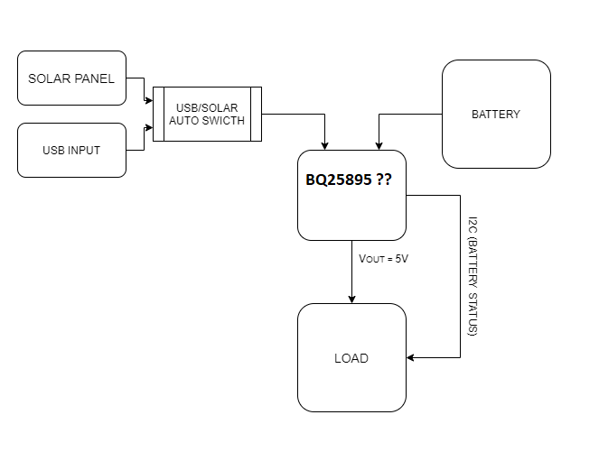
I simply drew the scheme I wanted to use. Is BQ25895 a product I want

The first time I am trying to design such a system. Can you help in detail I don't want to skip any small point. 


Regards,

Mehmet

  • Hi Mehmet,

    The BQ25895 output voltage can only be the maximum of either the battery voltage (e.g. 4.2V) + 200mV or the minimum system voltage = 3.6V typical.  For 5V on the output, you will need to add a boost converter following the charger.  Also, when charging from a high impedance source, like a solar panel, you will need to use the charger's VINDPM feature to implement MPPT and prevent the charger from collapsing the solar panel.  To implement MPPT with the BQ25985, you can refer to the reference design at the link below: 

    Regarding Q1 A, if the battery voltage is greater than the panel voltage, the charger effectively stops charging and enters HiZ mode.  

    Regarding Q1 B, if the output power at SYS is more than the input source can provide, the battery automatically supplements the system load.

    Regarding Q2, see reference design above.  The panel voltage should have 80%*VOC~=VMPP> VSYSmax+VSLEEPmax = 4.2V+150mV+370mV = 4.720V and ISC>100mA.

    Regarding Q3, the battery automatically supplements the SYS load if there is not enough input power.

    Regarding Q4, assuming the panel has enough power to pass the charger's poor source detection at power up, the charger will not pull more than its input current limit setting or too much current that the input voltage droops below the VINDPM threshold.  The charger's minimum quiescent current (not charging) is actually in the 3-10mA range.  The reference design mentioned above explains how to write software to find the VINDPM setting that will pull the MPP from the panel.

    Regards,

    Jeff

  • Dear Jeff,

    Firstly, i'd like to thank for your quick reply. I've a few more questions for the charging side.

    1-a.) Could you please give us more explanation about HiZ Mode? Also, when battery supports the load in HiZ Mode (Psolar is not enough for output), is that possible to feed output with solar power or only will the battery power be working? (Pin = Psolar + Pbattery or Pin=Pbattery)

    1-b.) Is that possible to charge battery, while the battery is feeding the load in the same time? We think it's not possible but we'd like to be sure.

    2.) If the solar power is enough to feed the load (Psolar_input > Poutput), is that possible to charge the battery? I mean, can Psolar feed the load and charge the battery in the same time?

    3.) There is an example to communicate with MSP430 in the TIDA-01556 document. Is that possible to use any MCU to use for i2c communication and get fuel gauge information (Raspberry pi, CC2541 etc.)?

    Regards,

    Mehmet

  • Hi Jeff,

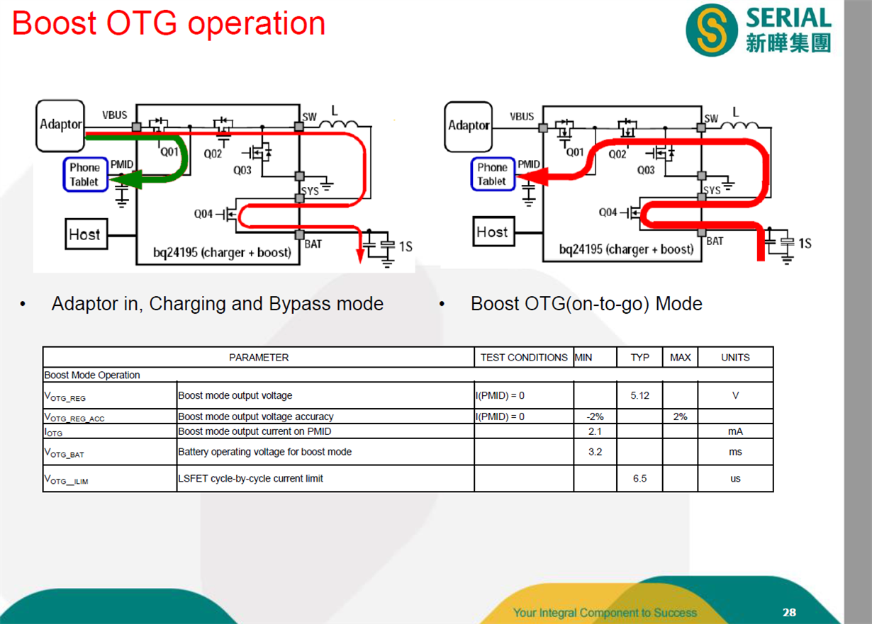
    - You told me to put a booster after the charger for 5V output. Can you tell us why we don't use the PMID pin?

    I found something like this for the second question (Psolar_input> Poutput) I just asked.As far as I understand, in this case, both the charging process can always feed the load. As soon as my input power is off, I can switch to boost OTG mode at the same time.

    Do you think it is right to think like that based on what I found?

    Regards,

    Mehmet

  • Mehmet,

    The charger works in either charge or OTG mode, not both at the same time.  There is a short (<100ms) delay for the switchover.

    Regarding 1a, HiZ mode turns off the buck converter and puts the charger into the lowest power state. The battery FET is always on to support the system load.  There is a user bit to turn off the battery FET. 

    Regarding 1b, if there is enough input power, the buck converter charges the battery and powers the system at the same time.

    Regarding 2, yes.

    Regarding 3, yes you can use any processor that can perform I2C communication.

    Regards,

    Jeff

  • Mehmet,

    One more clarification.  The PMID=5V output is only available when VBUS is less than UVLO~=3.6V, i.e. when no input adapter is applied.

    Regards,

    Jeff

  • Hi Jeff,

    - How can I follow a method to separate usb or solar input? In fact, I am doing mppt when solar input is available, assuming I replaced usb with auto switch as in the picture above, how can BQ25895 detect this. (without solar when usb)

    - For some questions you suggested using TPS2121 with BQ25895. which actually changes automatic entries. When it comes to usb, it will not be mppt. There is a little confusion about it.

    - I used this for battery fuel gauge.BQ27542DRZR-G1  Can you suggest an IC chip that I can use more simply than this?

    - I used TPS61230ARNSR for booster and it works fine. I plan to use it in this design as well.

    Regards,

    Mehmet

  • HI Mehmet,

    A diode OR (two diodes with cathodes connected) is the simplest method but also has the most loss.  The TPS2121 is a good option to replace the diode OR.  The BQ25895 will not know/care which power source is applied.  Since the USB source is low impedance, the charger can still run the MPPT algorithm with a USB source.  If you use the TPS2121, the u-controller/processor can monitor its ST output and disable the MPPT algorithm when USB source is applied.

    Unfortunately, I do not support the fuel gauges.  I can move this thread to the gauge forum or you can start a new thread.  Please let me know which you prefer.  I suggest starting a new thread as this one is long.

    Regards,

    Jeff

  • Hi Jeff,

    Thank you very much for your help. You've been very helpful.

    Regards,

    Mehmet