This thread has been locked.

If you have a related question, please click the "Ask a related question" button in the top right corner. The newly created question will be automatically linked to this question.

LM5050-1: Current Sharing Controller to combine two or more 50V 10A power supplies into an a single 50V 10x (20A, 30A etc) rail

Part Number: LM5050-1
Other Parts Discussed in Thread: CSD18563Q5A, , UCC29002

Dear Sir / Madam,

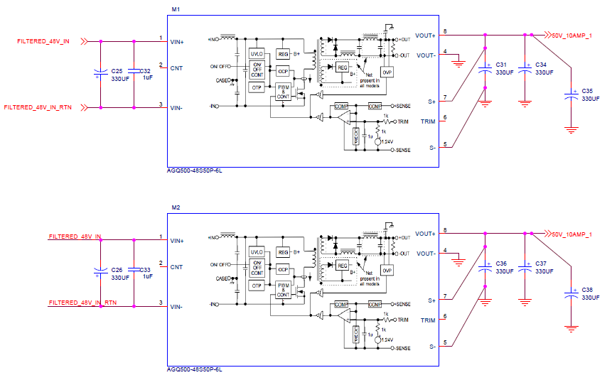
We are looking to use TI's UC29002 and LM5050 to build a current sharing controller to ensure that current is evenly divided and combined into a single rail. I have drawn up a schematic to show to two sets of Artesyn 50V 10A power source being used with UC2002 and LM5050 for current sharing, I might probably add more path to merge into a 50V 30A rail (below only two merging paths are shown). 

I may have a version with five 6A sources using these parts to merge into  a 50V 30A rail.

I appreciate if someone could review this and let me know their comments and also would this work as a current sharing solution.

Thanking you for your kind assistance.

Rajesh

  • Hello Rajesh,

    Thank you for posting the question on load current sharing.

    We will review and get back with detailed comments early next week.

    But we also have an application note about current sharing and it is a good reference.

    www.ti.com/.../slua550.

    Could you refer to this as well?

    Regards,

    Kari.

  • Dear Karikalan - vanakkam !

    I have already gone through SLUA550 TI document and have tried to follow the diagram "Figure 2" of SLUA550 document as best possible in the schematics I enclosed.

    Please help to review.

    The MOSFETs used are CSD18563Q5A.

    Let me know if I missed anything.

    nandri !

    Rajesh

  • I think I have to swap the signals "FILTERED_48V_IN" and "FILTERED_48V_IN_RTN" at the inputs of M1 and M2 as FILTERED_48V_IN is more negative voltage terminal which has to go to M1, M2's negative pins and the more positive FILTERED_48V_IN_RTN has to go the positive pin.

    Rajesh

  • Hello Rajesh,

    Vanakkam.

    I have tried to look at the schematic, it is not easy to read the values of components and connections as well.

    Can you please share better visible schematic, in a PDF or other formats?

    Regards,
    Kari.

  • ORAN_POWER-6-7-2020.pdf

    Dear Kari, Vanakkam,

    I attached the PDF schematics. Let me know if you are able to open.
     page 2 and 3 is where I am trying to do rail current merging on pages 2 and 3.
    Thank you for your kind help and assistance.
    Nandri,
    Rajesh
  • Hi

    I have reviewed the LM5050-1 portion of the circuit.

    MOSFET orientaiton of Q3, Q6 and Q8 are incorrect. Drain of the MOSFETs should connect to 50V_20AMP rail.

    That is source should be connected to IN and drain should be connected to OUT.

    MOSFET rating is 60V and this may not be enough for 50V application, marginal. 80V FET would be good.
    MOSFET RdsON is higher and may not support 10A. You may need to find smaller RdsON MOSFET to meet the power dissipation requirements.

    On the UCC29002 controller, sense pin connections from UCC load share controller to the 1/4 brick module is not correct.

    Let me request the expertise of UCC29002 team.

    Regards,

    Kari.

  • ORAN_POWER-9-7-2020.pdf

    Dear Karikalan, Vanakkam,

    I have replaced Q3 and Q6 with Infineon IPT015N10N5ATMA1 which has VDS of 100V, RDSon up to 2 milli ohm, VGS up to ±20V. THis is the best I could find. I also swapped the source and drain connection as per your comment.

    I have tried to connect the senses as in the TI app note, I am not sure if I doing correctly, Please help in checking this sense connections.

    I made another change in the schematics, I also moved the in rush MOSFET circuitry to the load side.

    Please check if I need to make any correction in the UCC29002 circuit.

    ungal udhavikku mikka nandri !

    Rajesh

  • Appreciate the kind review and comments on the updated schematics posted on July 9, let me know if anything got missed out in UCC29002 or LM5050-1 sections.

    Thank you for your kind help,

    Rajesh

  • Hello Rajesh,

    I reviewed the schematic and the UCC29002 data sheet.  I think you might be having issues because you are trying to load share 50 V outputs.  Sensing the current on the high side with CS+/- that have a rating of 15V maximum the amplifiers will not function correctly.

    It does not appear that the UCC29002 was designed for these high voltage applications.  I am going to discuss it with the applications team internally to see if any one has made this device work for applications with output voltages greater than 15 V.

    I have load shared peak current mode controlled step down converters on the primary.  You just need one feedback loop and control all the modules FB pins with this voltage.  This will force all the modules to load share.

    Are you using peak current mode on the primary.  If you are this could be an option for you.

    Regards,

    Mike

  • Mike,

    Thank you very much for your comments.

    These are standard Brick sized off the shell Isolated -48V based  DC to DC regulators which we are trying to do current sharing. 

    I see that Flex Power Modules app note : https://flexpowermodules.com/documents/fpm-designnote006-using-analog-isolated-power-modules-in-parallel-configurations also refers to the TI chip UCC29002D for current sharing, so it appears this IC is being used for supplies higher than 15V such as 48V used in Telecom.

    I hope I get the schematics right.

    As per you comment, I have moved the sense resistors to the ground side, refer to page 5 of the   updated schematics attached. Let me know if something is missed out.

    Thanking you once again for your valuable review and comments.

    Rajesh

    TRIBAND-PS-27-7-2020.pdf

  • Hello,

    Thanks for sharing that app note with me.  It does appear that  you can use the UCC29002 with output voltages greater than 15V with low side return sensing.  They use an NPN transistor to drop the voltage at the adjust pin so it is not exceeded.

    If you need anymore help let us know?

    Regards,


  • Mike,

    Please let me know if there is anything which needs to be corrected in the current sharing circuit in the last file attached.

    If the current sharing circuit looks OK, you could go ahead and close this case.

    Thanks for your kind support,

    Rajesh

  • Hello,

    I reviewed the schematic and looks very similar to the Flex application note.  So I believe it should work.

    There is an excel tool that you can use at the following link so you compensate the loop (CSO).

    Regards,