This thread has been locked.

If you have a related question, please click the "Ask a related question" button in the top right corner. The newly created question will be automatically linked to this question.

UCC28950: seperated vbias , transformer turn ratio and power rate..

Part Number: UCC28950
Other Parts Discussed in Thread: UCC28951

Hi team , i will design three or more dc/dc converters like 24V 100A output , 12V 200A output

1-is that possible with the ucc28950?

2-But i got a problem in the design of the transformet turn ratio why is the turn ratio calculated with 0.7 times in the datasheet says that he must give a room what does that mean? 
What if we design a system without a pfc?

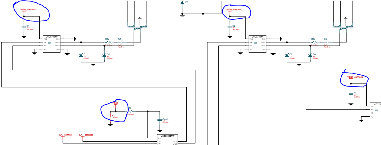
3-in the picture below there are Vbias1,Vbias2,Vbias3 and Vbias connections does this mean that they are seperated? do we need supply the IC's and the drivers with 4 seperated supply?.

Thanks in advance


  • Hi

    The UCC28951 is a good choice for DC/DC isolation stages running from a high voltage input like a 400V bus from a PFC stage.

    The datasheet calculation for the turns ratio is specifying a 70% duty cycle at the minimum input voltage this will allow the design to maintain output voltage regulation during load transients if the input voltage is been supplied by a PFC stage which normally has a slow voltage loop. It also allows output voltage regulation to be maintained for a period of time when the input is disconnected.

    The driver and controller can be supplied by a common bias rail. Please pay attention to the UVLO turn-on and turn off levels of the driver IC and the controller to ensure the drivers are operational when the Controller is active.

    Regards

    Peter